Page 1 / Page 2
I need an aerobatic trainer. I have flown Mike Myers' Mountain Models Magpie and like it, so I thought I would build one, or something like it.
It must be easy to build and rugged so I will build it in foam. But then I thought if I build it from scratch it need not be a slab sided monster. It could be a scale airplane with similar dimensions.
I like my B-24 or older "Bristol Freighter" both of them built from foam.
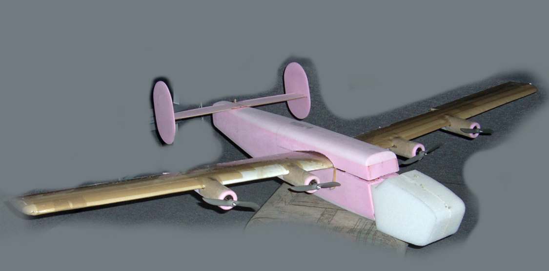
My first one was the Bristol Freighter, started as a box fuselage and empenage made from Corning 1/3 inch Fanfold pink foam. Having made this much I thought I had better turn it into a complete plane so I ended up learning how to hot wire wings. My work was not very successful as I probably cut a dozen to get two passable wings. I finished the nose with soft spongy foam from some packing. This turned out to be an excellent approach because it saved the plane many times from various arrivals with the heavy NiCad battery pack buried in there. For propulsion I just decided to make it a twin using two Speed 400 7.2 volt direct drive motors. It flew well right away and has been a good airplane for years.

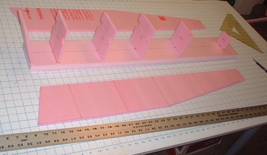
I then started to build a B-24 for four speed 400 motors. For a model this size I added some balsa reinforcement. See the notches in the fuselage formers.
White or yellow glue works fine to assemble these parts as there is sufficient air adjacent to the glue line for the glue to set. You can't use this glue on foam parts where the joint is buried. It will never dry. For such joints I now use polyurethane glue and add some water catalyst (spit on or lick one of the parts).
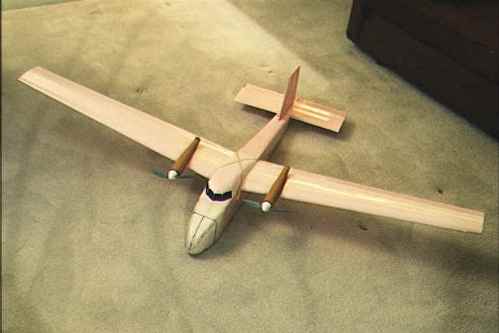
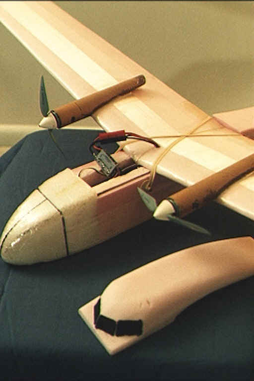
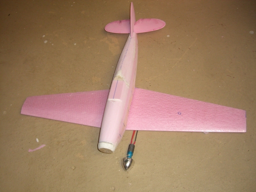
I originally wanted this to be a fairly accurate scale model so I ordered some wing blanks from one of the cutters, however, in the meantime I wanted to test both the propulsion and aileron control as I did not plan to actuate the rudders. So I built a propulsion test bed. This is the test bed but for some reason this is not what I flew, although the wing is the right one.
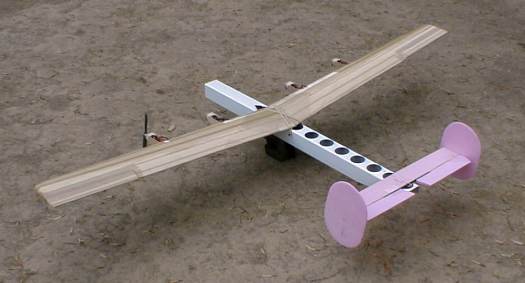
The basis was an old Hobby Lobby Spirit of 76 six foot span foam glider (kits were $25 in 1996) It worked well but I put the project aside for a long while. Then our club decided to hold a Cox Warbird Day and I thought the B-24 would be a good addition to the fleet as we could fly bomber escort missions (or attack missions for the Bf-109s!).
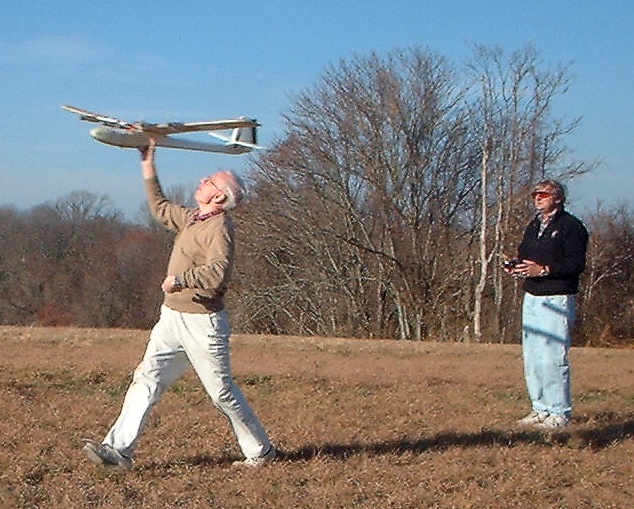
So I completed the B-24 just using the wing from the glider. As with the Bristol Freighter I fitted a soft foam nose. Fortunately this has not been tested so far despite missions carrying Winston Churchill to Moscow and Casablanca.
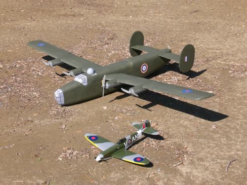
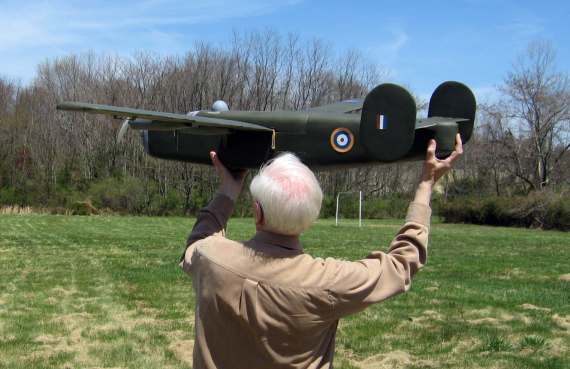
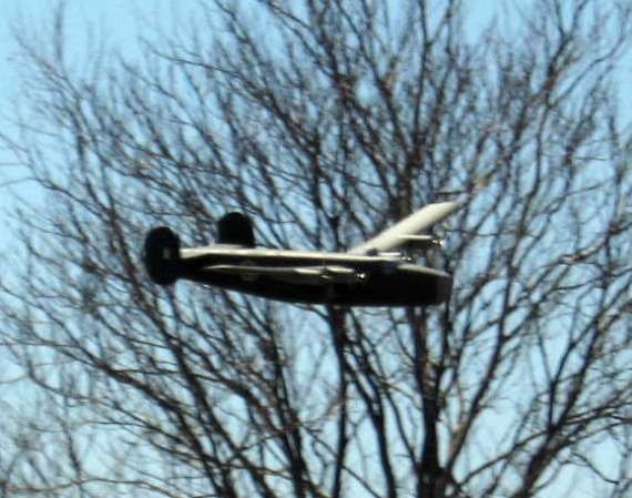
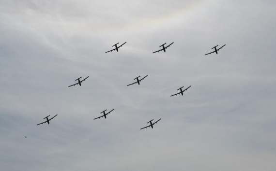
Good grief, there is a squadron of them on the Ploiesti raid! They got through too as all the Cox Warbirds succumbed to one malady or another. The B-24 lives to fly another day.
As an aside at this point let me tell you a related story. Back in the summer a fellow stopped by our field as a few of us were chewing the fat waiting for the wind to abate. He said "hi, my name is Bill Fili and I would like to join your club" Of course we said that would be fine and asked what he would like to accomplish. He said he would like to learn to fly because by next spring he would have completed a 14 ft span, four engine B-24 model, and he would like to fly it. Well it is not unusual for potential new members to express such aspirations and with a few private chuckles we always encourage them. One of the guys asked if there was any special nose art he planned to apply and Bill said oh yes it is the Destiny Deb. We then asked if there was any personal significance to this particular B-24 and Bill said "yes, that is the one we were flying over the Ploiesti oil fields when we were shot down". Ok Bill, any dream you want is ok with us! Then he said I expect this will be the only club in the country with a flying four-motor B-24. Beg to differ. Come on out next weekend and see our B-24 fly at the annual picnic!
So, back to the aerobat I wanted to build. After scratching around for a while I decided that this was also an opportunity to take another step along my plan to build one of each of the significant Hawker aircraft; I was a Hawker Aircraft apprentice after all.
First the 3-view, and you can usually find one on Eduardo's Page
Open Corel Draw and import the image then stretch it to the right dimensions, usually the wing span. then you can draw the outlines and construction details you need on another layer. In this case I also imported a scanned image of the Earl Stahl Hurricane as it has the cross sections in the form of formers.
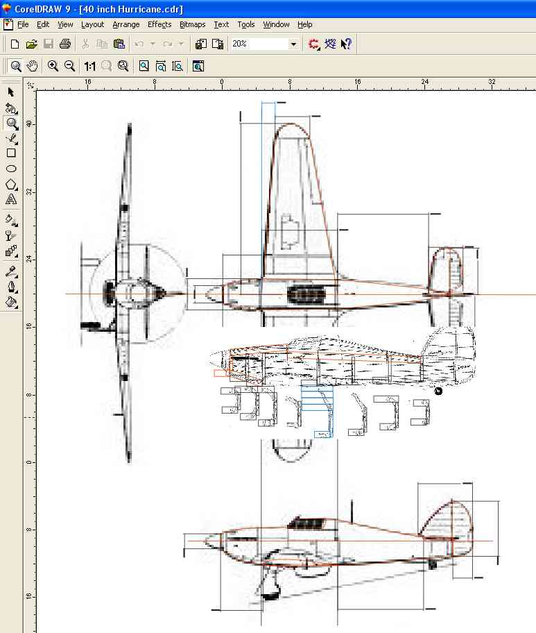
Then I could size the various parts. The fuselage is made from the fanfold foam sides with a couple of ply formers and 1 inch foam bottom and two inch foam top. The top is split at the cockpit aft bulkhead and here I installed two bulkheads, one to be fixed to the fuselage and the other to form the back end to the upper cowl. I made the first inch of fuselage from two layers of 1/2 inch balsa with a ply front former to which I fasten the motor.
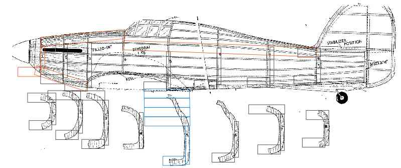
Here is how you accommodate the foam sizing so as to be able to shape the blocks and not have it fall apart because the corner was cut out! I decided to make the sides from Fanfold then insert a shaped piece of 3/4 inch foam within the sides to form the bottom but place a 2 inch piece of foam on top of the sides to form the top. You get the shape and size of these parts by laying out how the foam will fit onto the cross sections as shown below. I placed rectangles depicting the foam blocks on the cross sections from the Stahl formers They were shaped and placed so as to be able to shape to the final shape yet leave sufficient material for good glue joints. The dimensions for each initial sizing were then placed on the side view so that they could be faired into complete parts. Adjustments need to be made so the individual parts aligned. For instance the top block would fit on the top edges of the sides and this joint would be a straight line, or a smooth curve. This drawing shows the top blocks in red, although this is not the final as-built design because i made changes to simplify it and accommodate available materials. Hope you get the idea, but maybe you have to do it for yourselves to really understand the process.
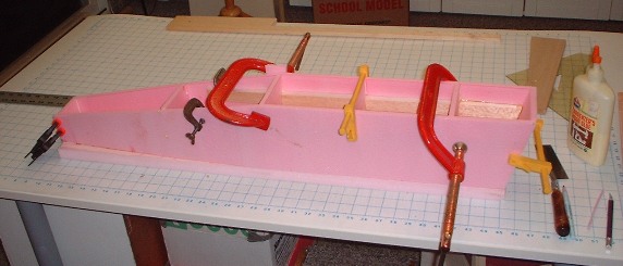
I scarfed the back ends of the side members then glued them together.
Following this I inserted the bottom blocks and similar part at the top back portion of the sides. This was followed by the balsa and ply nose pieces.
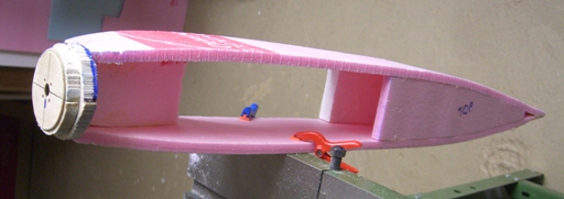
This view is the top side without the subsequent upper fairings.
I struggled with how to make the wings and eventually decided to try hot wire again; What a disaster. Best forgotten until I feel the urge again.
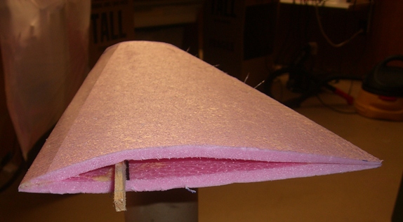
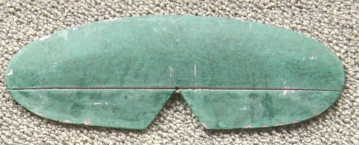
What to do? Well some years ago I made a wing structural test piece using the Fanfold foam for upper and lower skins with just a spar for separation. So I decided to give this method a try. I laid out some airfoils for tip and root and assessed the degree of scarfing required and the spar dimensions. Here is the finished Hurricane wing. Note the tape on the leading edge, this was an essential part of the fabrication process as all my other attempts resulted in parts and glue each with a mind of their own and my inability to clamp them into an assembly. Actually, this is not the final wing because the leading edge formed in this way is far too sharp, especially for an aerobat. So to complete the shaping I cut 1/2 inch off the nose and blended it with a generous radius into the rest of the "airfoil".
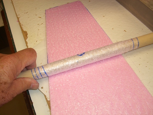
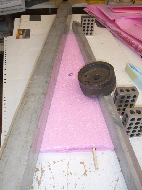
The first step in wing fabrication is to cut the blanks then remove the surface film. The old stuff did not have such a film but my latest batch does. You peal up a corner then wind it onto a dowel.
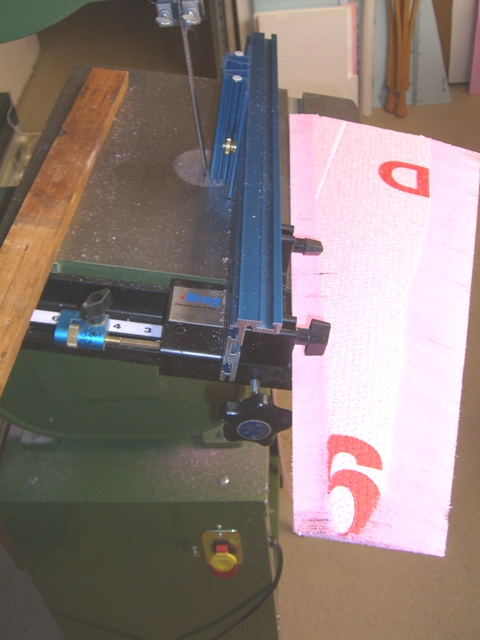
Then you scarf the LE and TE, note the scarf angles are different.
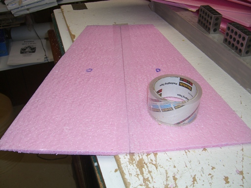
Then you join the two skins with tape so as to hold them together but allow you to fold them over.
Then you prepare all the parts including the spar and additional graphite reinforcing if you like, and I do ( I have to use the stuff up someday).

You butter every joint with polyurethane glue and spit, then align them and clamp the assembly.
Update; for those who read this earlier, note there is a wedge put under the trailing edge prior to applying the weights. This forms the airfoil into something like the so called semi symmetrical shape. Just what I need for this aerobatic model. I could have forced it into a full symmetrical airfoil with a larger wedge and a similar piece under the leading edge should that have been my desire. But I thought a full symmetrical section would look out of place on this model.
Don't forget to make a RH and LH wing! I joined the two halves with a couple of joiners and more polyurethane glue. This is extra good stuff because it foams up and fills the voids if you leave any. You can't inspect the joiner after you offer them up for gluing!
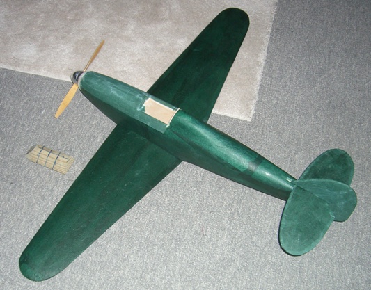
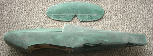
Here is the completed foam structure. The foam blocks were formed with a combination of band saw, knife, rasp and long sanding bars. It is an easy task but you must remember not to remove too much at a stroke. It is fairly easy to glue a block back in to fix a deep cut but you must be careful to ensure the glue does not peek through the finished seam. The glue is much harder to sand than the foam and you will end up with a hard line. Better to plan ahead and ensure the glue remains buried after the final cut.
The wing is located with a dowel into a ply cross member at the LE and a nylon bolt at the TE. Local light ply parts were glued in place to accommodate the higher loads from these areas experienced on hard "arrivals".
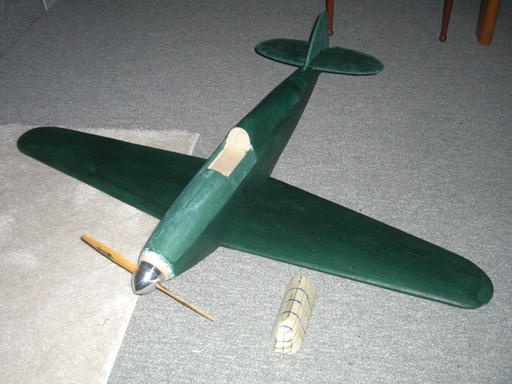
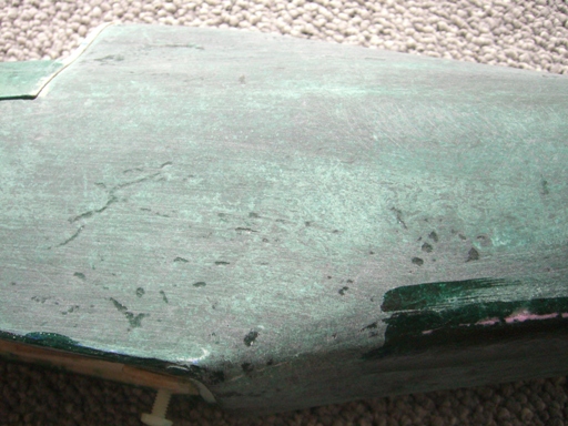
The Bristol Freighter and B-24 were finished with heat shrunk packing tape and spray paint, but that method bubbles up and needs constant shrinking, but it is fast. For the Hurricane I wanted a better finish so I am using the process I use for the balsa shell cowlings on my SAM models. I cover them with inexpensive wrapping tissue and water based polyurethane sanding sealer. I apply quite a few layers allowing them to dry and lightly sanding out the creases between coats. Dings and other warts can be filled with lightweight spackle. Here is the Hurricane with a couple of layers applied;
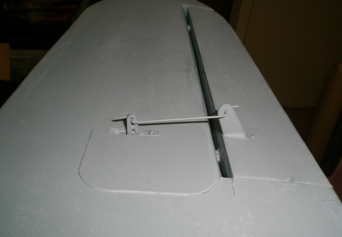
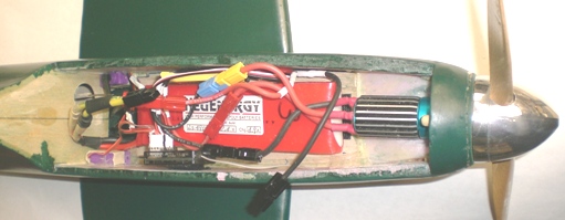
This shows how the upper fairing is removed. It is keyed to a dowel at the front and will have a catch at the back. You can also see the lightply reinforcing at the front and rear of the wing opening, well you can see part of it. I have also installed a deck to handle the battery and other stuff inside. Also in the picture is the buck for forming the canopy. I will be searching through my stash of bubble packaging to find one with the right size and amount of draw so I can reshape it into the Hurricane canopy form.
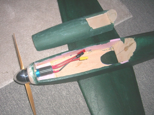
I plan to use the Model Motor Extreme motor running at about 25 amps on a big two-cell Lipo. The spinner is a 50 mm unit from BP Hobbies. The model with motor but without controls and battery currently weighs 20 ounces. Maybe 30 ounces finished with a wing area of about 260 sq inches. Should be fine.
I will cut the control surfaces from the wing and tail once the finish is complete less the final color painting. I will use Robart hinge pins. I think I will install the tail servos in the aft fuselage and I plan to use two aileron servos.
So, watch this space, but you know, I think this will turn out too nice to be an aerobatic trainer so I may have to build a slab sided monster after all.
Monday 24th November.
I have finished sanding the base coat. It may not be done as I wished, but I have declared it done! I will have to refine the process if I do it again as it was much too time consuming and messy. The biggest problems were the poor wet strength of the cheap tissue, that did not allow me to smooth it when wet, and the unavailability of the water based sanding sealer.
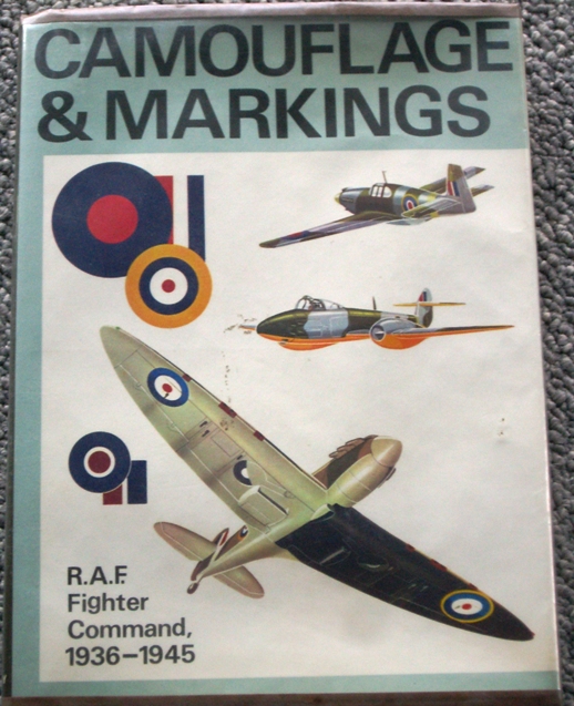
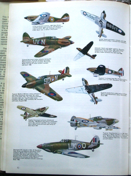
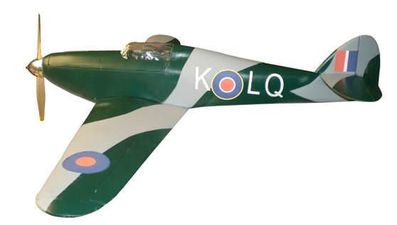
It is not my intent to make a true scale model, just one that looks right in flight. So I have been buying rattle cans of likely colored flat cheap paint and took them to Mick's for a review of my options. I had no idea there were so many variations in RAF fighter color schemes throughout WWII. We came up with several options that I will continue to mull. Interestingly enough, I really need a color scheme that allows me to maintain visual orientation; up down right left, and the Battle of Britain colors featured a lower surface with black on one side and white or sky blue on the other. The upper surface being the common dark green and dark brown camouflage. Mick suggested I consider the excellent Tamia water based enamels available in the hobby stores for plastic modelers. He says they brush on beautifully. My preference is to spray the large areas if the weather cooperates, then add the detail.
Still need to wait for suitable weather for test flying, either that or bundle up and fly in the cold.
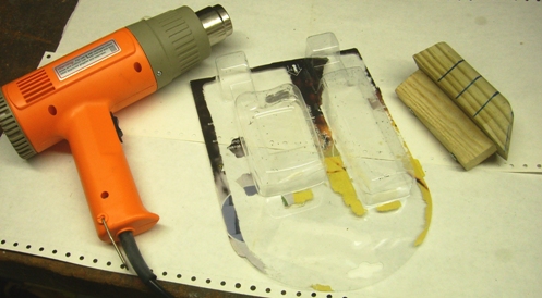
OK, but I don't want to fly without a canopy, it screws up the aerodynamics! So I sought out a suitable "bubble pack" and quickly made one. It turned out poorly with all kinds of wrinkles, but I was in a hurry so I taped it in place just for the testing. Shown here is the pine buck or form I made to size and the riser screwed to it so as to allow forming beyond the mold lines. The selected "bubble" is the one to the right of this double bubble pack. It has the right draw and length from which a good canopy should be possible, but I did not have enough hands to pull it down and aim the heat gun. Should have asked Jean to help but she was busy and I was in a hurry (as usual).
I had been stewing over ideas for a cowl latch, mostly trying to design one that would be unobtrusive; most associated with making the aft-of-cockpit radio antenna (the real airplane one) part of the actuation means. In the end I decided to use rubber bands for the testing and put off the latch decision till later.
Well, we did fly again, this time I had one of the good hands fly it but the result was somewhat similar. It flew out of a good hand launch but Brian immediately had problems with the left roll out of trim. He struggled all over the sky trying to gather it up but then it dropped its nose and spun in vertically from about 100 feet. I really don't know what is causing the problems. After the crash I gathered the parts and took them home to the shop. All the servos worked perfectly and cycled smoothly with the Astroflight servo stimulator. Brian commented that he had cut the throttle during the decent and it responded so the radio and ESC were still working and I have subsequently tested them again. So, not to fix the damage. On the positive side I built this model to evaluate the damage and repair aspects of an aerobatic trainer and although I had hoped not to do these evaluations this soon they were on the list to accomplish!
I will start page two for the next phase; Go to page 2