I have this urge to learn to fly RC aerobatics, not for competition but for fun, and for the same reason the military teaches their pilots aerobatics; to recognize, understand and recover from "unusual attitudes". West coast flying buddy Mike Myers has a Mountain Models Magpie and that fills the bill, so I built one too, but it is on the west coast so I wanted to build something similar on the east coast. This led me down the as yet unsuccessfulFoam Hurricane project.
Moving further along the path of the easy to build, easy to repair or replace aerobatic trainer I decided to build a foam delta. I had seen some in California and one of our club members has flow a simple lightweight one for years.
There are two different Fanfold Foam products, the blue 2/10 inch foam from Lowe’s and the pink 1/3 inch foam from Home Depot. Joe uses the blue foam as his models are quite light and usually feature modest power. This one is actually a modified saucer rather than a delta. It is powered by a small outrunner and uses a Thunder Power lightweight series 1000 mah three-cell LiPo. This picture will give you the shape to use and you could build one in any size with any power.
In the January 2008 club newsletter I reported on a flock of foam planes by a Pasadena woman; Chellie. Her planes are depicted on Watt flyer Just do a search on threads by Chellie or go to;
http://www.wattflyer.com/forums/showthread.php?t=16298
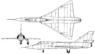
I started with a simple delta form then thought why not make it a scale or semi scale profile model while I am at it. So with Eduardo’s 3-View web pages in front of me I searched the hundreds of 3-Views for a suitable model. The one I chose was the Convair Delta Dart. Or at least I think I did. Maybe it was an F-102 or F-106!
Anyway, the process was the same; decide on a size, decide on tractor or pusher configuration, decide the elevon size and start cutting. I decided on a pusher arrangement.
Well, for reasons that only Freud may understand I have no photos of this model. Shame really as I covered it in lightweight packing tape then sprayed it silver to look like the real thing. Anyway, in a whole series of flight tests I never succeeded in achieving a satisfactory stable and controllable flight! It eventually succumbed to one final arrival into Christian Academy’s “flight testing tall grass” (an aeromodeling necessity Dick Seiwell). I ripped out the guts and dumped the rest.
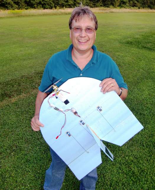
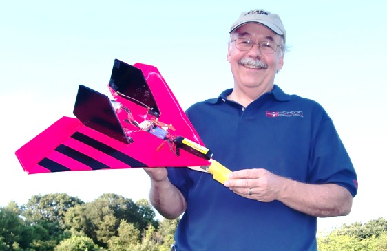
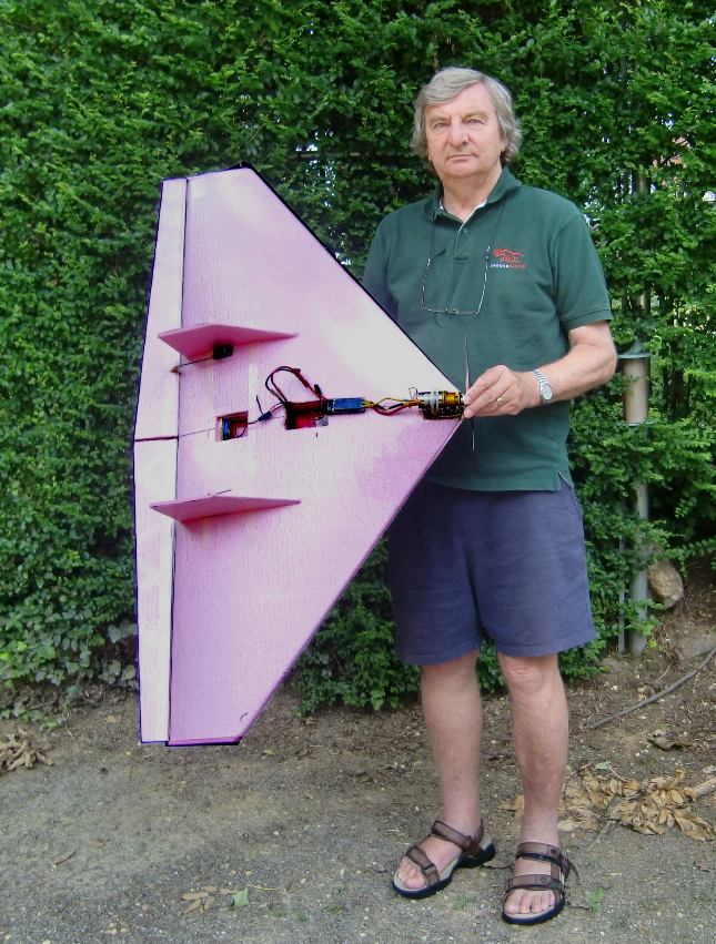
But not deterred I was attracted by the parts sitting on a shelf in the workshop. I should be able to build a satisfactory model with that motor/prop/ESC and the pair of servos with control horns and push rods attached. So I cut out another simple delta, shown here with my #1 grandson Matthew.
Well, even that is not strictly true as when I look at it I recognize several modifications that were required to tame the beast.
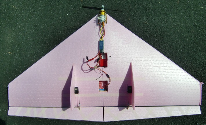
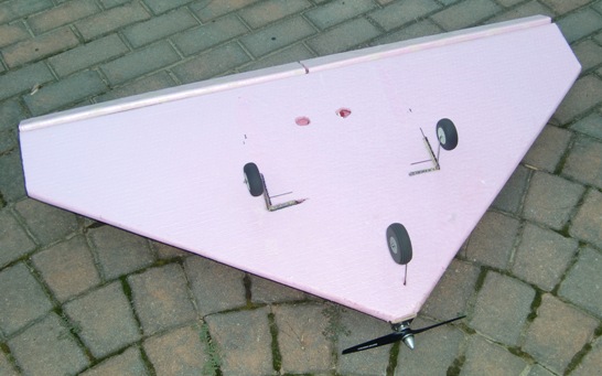
Here is the plan view as it stands today after several modifications that have made it a pussy cat and joy to fly. The original was built as an 18 inch span 14 inch long pure delta with a pusher speed 400 6 volt brushed motor and a 1000 mah LiPo battery.
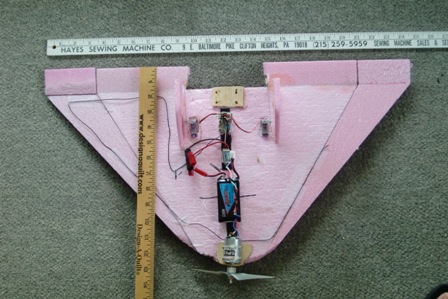
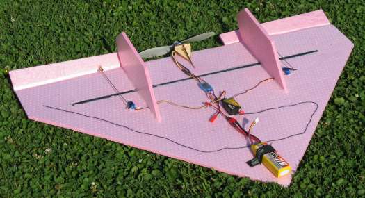
The receiver, ESC and battery were arranged along the centerline on a strip of Velcro so as to bring the CG to the desired point. The servos are pushed and glued into the foam and pushrods / bellcranks arranged to give the desired travel and initial trim positions (it is probably better to use adjustable ends so as to make the necessary trim changes should they end up beyond the servo / transmitter adjustments.
Well, my initial trials did not go well as you would remember from a series of Tuesday morning and Christian Academy trials. At first the model would go into a flat spin, sometimes inverted. I was disgusted, how could I be so far off, I have built HL and catapult launched deltas in the past. What to do? Ah, the age old solution; build a hand launch glider and get it trimmed. Hmmm… build nothing, I have one, just leave off the motor, battery and receiver, lock the elevators in position and add nose weight to suit. Well, the first lead sinker I selected was perfect right out of the box as they say. I was so pleased I immediately went to Mick’s to demonstrate the nice flat stable glide in his front yard. Now what?
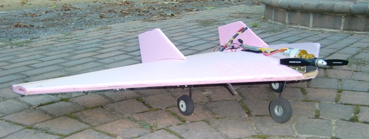
The answer was to put the model back together and get the CG in the right place; 50% back from the pointy nose. This required the motor be installed on the nose as it would have taken a ton of extra weight to counterbalance a pusher.
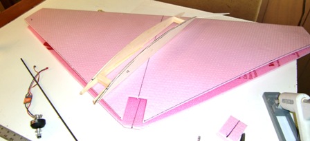
Ok, now let’s try it again; wow, it flies but the controls are so sensitive in roll. I am all over the sky and in the ground on occasion; but it flies! Now what? Well, I increased the span and wing area by adding the spanwise strips to the leading edges as you can see in the picture.
Furthermore, I added fixed “elevons” to those panels and this modification has done the trick. It is really a pussy cat now. I can even let the CG go a little more aft to reduce the up elevator trim required. However, subsequent flights where I have tried to get axial rolls indicate insufficient down elevator authority. I think I will eliminate the up-elevator on the fixed portion and make them flat. This will require a bit more elevon up travel to trim right-side-up but less down elevator to achieve inverted flight trim.
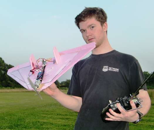
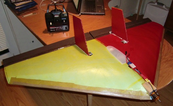
Meanwhile, in parallel with the above developments once I learned where to put the CG I decided to build another larger more powerful version. I based it on a commercial model using the same geometry. It is covered with low temp film which worked well. They need a distinctive color scheme to see which way is up! This 30 inch span model with an Aveox brushless pusher motor required a ton of lead in the nose for balance and in my first couple of flight attempts I found it to be a monster with very twitchy roll response. Monster, who can fly those? Rick Grothman of course, so I asked Rick to try it at a recent field day. It took his son Paul to throw it hard enough to get flight speed before kissing the ground but it flew and he brought it back in one piece although he didn't’t tame it.
So back to the drawing board and try the same fix I had subsequently developed for the smaller model. In this case I cut about 1/3 off the elevons and fixed them at a small up elevator position. I also removed some nose weight making the model lighter and moving the CG a little aft. This worked well with this model too and it is tame enough for me to fly now, although the howl of the Aveox turning the 7 x 6 APC electric bothers our President!
Meanwhile I had created another monster; Rick just had to build one for himself and a few days later he sent me his results. Here is his 30 inch model with a small outrunner. His model has a graphite tube spanwise for stiffness as shown below. I had the same thing on my larger model but I put it at the fixed trailing edge. All these models also need a hard balsa keel glued on the underside and connected to the motor mount. This provides a secure fastening for the motor and something to grip firmly on launch; a necessary feature especially if the model has a pusher motor. Watch out for those spinning blades on launch. Rick’s flies great too. Rick says “ Thank goodness for computer radios with exponential, I was surprised how smooth it flew after getting it trimmed and LOTS of exponential (maybe shorter servo arms?)”
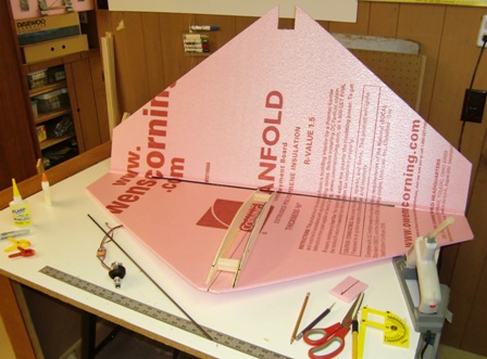
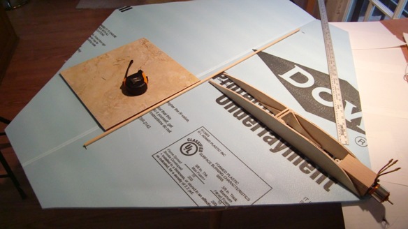
But all this twitchy flying properties with these small deltas are more than I am comfortable with, so what if I built a big one? Let's see, the basic sheets of Fan Fold foam are 48 inches by 23 inches. That would be a good starting point so I began to lay one out. I thought I would make it a two-layer structure with a pair of longitudinal ribs spaced so I could put the batteries inside, protecting them from the abuse my LiPos have received from surface mounting. Also the spaced ribs would provide a base for a motor mounting platform. I thought about tractor and pusher designs and selected a tractor because this big guy might be hard to launch and I am quite concerned about the safety of launching the pushers (maybe a ducted fan...?). Here is my initial cut at the structure. I decided to make the trailing edge the natural foam fold. I cut the two ribs from hard 3/16 inch balsa, reinforced them at the forward end with a tapered piece of 1/8 inch x 1 inch pine and joined them at 2 1/2 inch spacing. Note the notch in the front for the motor mount. This is essential also to allow for the subsequent forming of the upper surface to the ribs and leading edge. Also shown in the picture is the graphite tube I installed at the trailing edge before closing up the structure. It does not run over the complete spanwise length but stops several inches short.
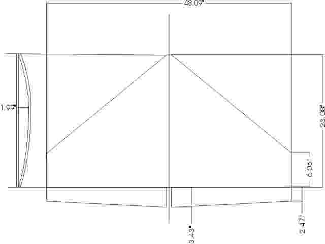
Sorry about the Mickey Mouse dimensions. If I had more time to master Corel Draw........ Just round them off to the obvious dimensions, or use your own.
Then I glued the ribs to the lower surface using hot melt glue.
Then I glued the top half to the ribs also with hot melt; work fast!
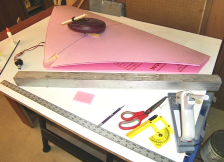
Next comes the tricky bit; gluing the leading edges together. This must be done on a large flat surface. First make a trial fit by pushing the upper leading edge down to the lower surface. Mark where the two come together, it will be about 1/2 inch back from the lower leading edge. This is important because you now know where to put the glue. The next thing you will need is a long strong and stiff fixture that will hold the upper surface down uniformly to the lower surface while the glue sets. I use a 2 inch square aluminum rod shown in the picture above. I couldn't get a picture of this step as it takes 2 1/2 hands to hold everything in place while the glue sets.
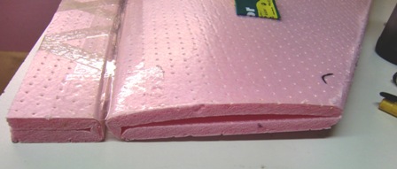
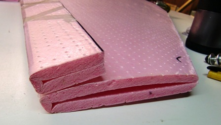
The next step is to cut the lower leading edge to match the top then sand the whole leading edge to a nice radius. I plan to finish my leading edge with two layers of brown paper soaked and attached with 50% thinned white glue. (But it was not accomplished for the first flights! You know how it is, the weather is great and its getting dark but you are close enough to finished to sneak in that first test flight!)
Next I made the elevons, also from the Fan Fold material. It is a good idea to make control surfaces at least as thick as the wing trailing edge they mount to, so what better way than to use the same Fan Fold hinge as the leading edge. So I cut the pair from another pair of sheets. I made them with a greater chord at the center tapered to the tips. My earlier deltas were Ok in pitch but wickedly sensitive in roll, so the tapered surfaces would help in this regard by having a smaller area involved in the roll action. This was also the reason I modified the delta form to a finite chord at the tip. I mounted the elevons to the delta using 2 inch packing tape. I first taped them together on the top surface being careful to allow a small gap between the parts. Becasue these are long parts operated from somewhere near one end I wrapped them with a one-inch fiber reinforced packing tape to increase the torsional stiffness. I made long control horns from 1/16 inch ply and drilled three holes to allow for travel changes. These were glued to the surface by cutting slots top to bottom then inserted with five minute epoxy.
Next I flipped the elevon over on the top wing surface and added the second strip of packing tape. This forms a hinge on the top surface. It is also important to push the two tape surfaces together right in the small area of the joint.
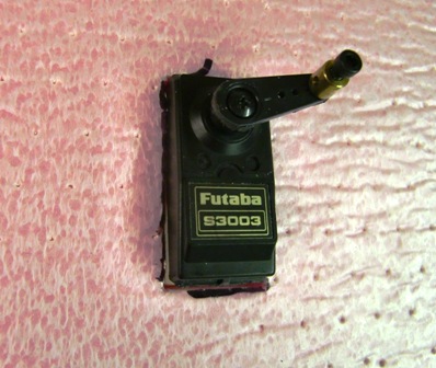
I decided to use full-sized servos as the surfaces are large and this beast could go quite fast. Also they are cheap and I had two hanging around for the last ten years or so. I mounted them somewhat outboard; a trade between putting them near the load center to minimize surface twisting and keeping them inboard to minimize roll inertia. I glued them in my usual way by first wrapping them in masking tape then gluing to that surface. I also wanted them to glue to both the wing lower surface and the upper surface edges to ensure the most secure attachment. This required padding the lower surface with the piece cut in the upper so as to raise the upper end clear of the upper surface. I also cut a hatch into the center section between the ribs to serve as a radio compartment. I wanted the radio to be behind the heavy stuff so as to avoid crushing it in a nose-in crash. This also let me run the servo wires inside for a neater appearance. I also ran the receiver antenna back out through to the servo bay then out through the trailing edge. This left a piece of antenna that could be taped into the control surface hinge without any hanging off the end.
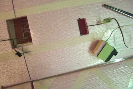
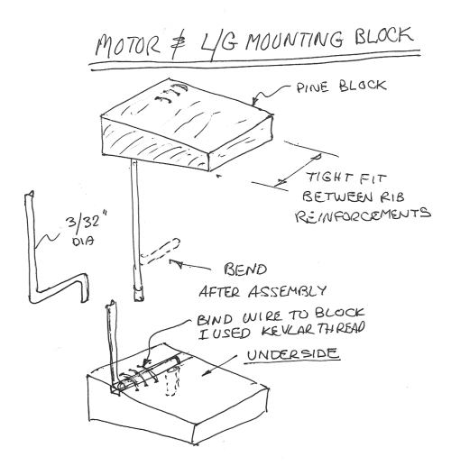
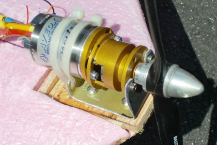
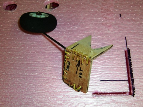
By now I had enough built and thought out to do a trial balance. Surprisingly it was about right on with an Aveox 1406/2Y with a 2:1 gearbox that I had laying around, and that was without the battery. I did some Motocalc runs and determined that the Aveox would be an ideal match giving excellent low speed thrust and high speeds with a range of props from 9 x 6 to 11 x 8. Now this motor is quite hot and turns these props at about 9000 rpm, so hand launching was becoming an issue and I decide to install a mono leg landing gear under the motor. I cut a pine block that fit between the ribs, tapered to match and yield down thrust. I cut the block so as to allow mounting of the L/G leg, which I bound in place with Kevlar thread. then glued the whole assembly into place. The motor was mounted on an aluminum mount shown here.
Then I cut another hatch in the center where I installed the battery, a Neu Energy 4900 mah two-cell LiPo; I just happened to have two laying around. My plan was to install the battery behind some soft foam blocks. This allows moving it back and forth in the long cavity to make CG adjustments as well as providing a safe environment to protect these expensive items.
When I assembled the complete model I found the ground attitude pushed the elevons to a high position, probably beyond the commanded position when the radio is on, so I added a pair of sub-winglets glued to the tips to keep the elevons out of the grass.
I was ready to fly and the weather was good and it was a Thursday evening fun fly at the field.
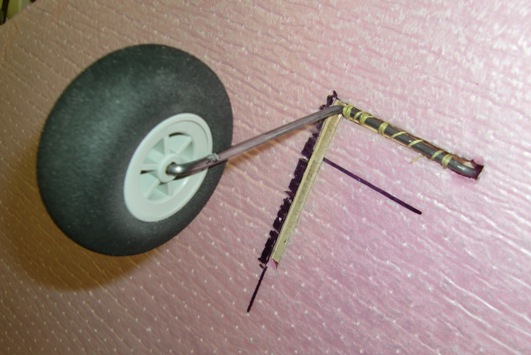
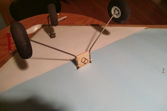
The first takeoff attempts resulted in a sharp left turn and spin out in the grass. Why? Well look at the wheel alignment.
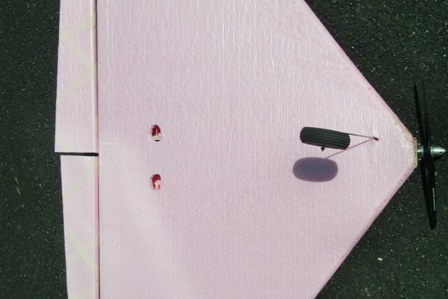
OK, now see if we can hand launch this beast. Where to grab it? I tried the landing gear and my fingers in the control hinge but couldn't get a grip. This resulted in a nose-in arrival. Ok, let Rick try it, but when he held it up we both thought a pair of finger holes would be a good idea, and an easy fix. So we tried again.
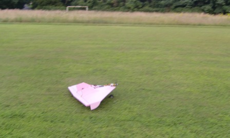
Still nose in! Why now? Well, the first arrival caused the battery to move forward under the foam block so the CG had moved forward too. We moved the battery back and Rick made an excellent launch and we were off for the first flight.
What a dream to fly! Trims were off particuarly the pitch trim. We ran out of Tx adjustment and had to fly holding in up elevator but the control response was just what I wanted; positive, smooth and not twitchy. I handed the controls to Rick who was also enthusiastic about the model. He landed and we adjusted the trims and control throws and made one more wonderful flight, exploring both high speed and low speed handling. Of course we all know deltas have great low speed handling qualities and performance and Rick made pass after pass low and slow down the patch.
This model is a winner and several of the guys want them. Better get back to the stack of Fan Fold, maybe I can make up some kits.
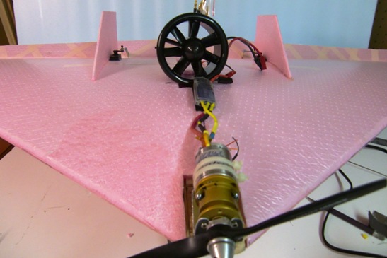
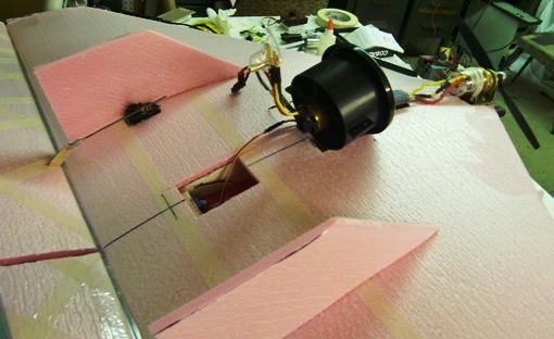
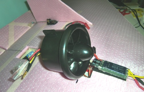
Rick suggested we should build several of these and try formation flying etc. Good idea, but what about other versions, like an Electric Ducted Fan, EDF? Well, I just happen to have a MiniFan from ten years ago or so, and I recently acquired a suiltable inrunner motor from Hobby City. Don't know why I bought this motor at the time, but it fits perfectly so I guess it must have been Karma, or something like that.
So I have been thinking about how to do it. In fact I was thinking about using this powerplant from the beginning but couldn't think of a satisfactory way to mount the motor. The housing has two lugs on opposite sides. I thought if I mounted it vertically from one lug it would be vulnerable in all kinds of ways. But subsequently I have thought about mounting it vertically but using struts to stabilize the unit laterally.
The other consideration from the experience of the two initial flights is a way to ease the launch situation and I decided it needed a full-up landing gear with steerable nose gear. So I developed a design concept to incorporate these features but preseving the simplicity and essence of the current model. Here it is;
Guess the construction will have to wait till I get back from vacation in late August. Maybe I can build it for the Walt Bryan Memorial Fun Fly on the 29th. Hmmmm.... wonder if I have time to get some retracts?
"Late August"
Well, I am back from the excellent but exhausting family vacation and have more enthusiasm about making the current plane more manageable than building a new one right now. The major problem is launching so I decided that I need to put a landing gear on this one. At first I thought this might be difficult, particularly incorporating the structure inside the already completed wing. But the more I thought about it I came to the realization that I could add new main gear, including an adequate structure by inserting it through lower surface slots. So here is what I did. First I designed a simple structure that would add longitudinal and lateral load carrying strength as well as fixing for the wire gear leg. This would incorporate a degree of torsional compliance as well as a little aft cant so vertical loads would tend to cause an aft compiant motion.
This structure needed to tie in to both upper and lower surfaces as well as the wire gear. I decided to make it from ply and glue and lash it together with Kevlar thread, then CA the whole thing. This is what it looked like before assembly.
As you can see I cut slots in the lower surface through which the structure can be inserted. I located the main gear just ahead of the CG and length to allow a slight nose-up stance.
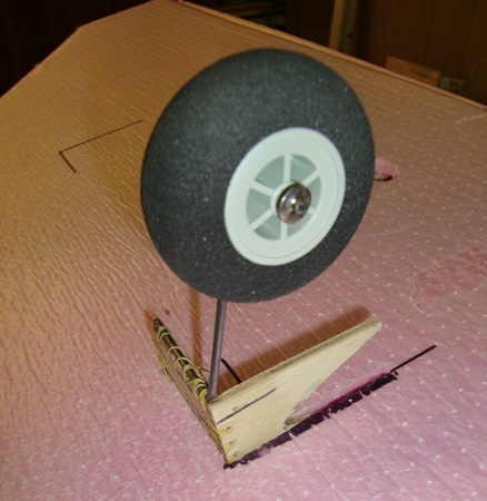
The structure needed to be glued to the upper surface to make a shear tie and also to the lower surface slots. I decided to use hot melt glue as it seems to work well in this application. I slathered it onto the bottom edges then partially installed it as shown above, the quickly added glue around the structure where it would attach to the lower surface. Then pushed it firmly in place.
It worked out pretty well as you can see here, but of course it needs to function before I declare complete victory, and we will probably fly this morning after breakfast. I wonder how it will handle the longer grass in Chester Park? Maybe I should take a couple of sheets of Fan Fold foam for an initial runway.
well, it flies great although it really needs nose wheel steering.
Just back from a very long stay at our daughter's house in SoCal where flying buddy Mike Myers and I have both built new deltas but with the 1/4 inch blue foam. the only difference in construction was the addition of a shear member spanwise to stiffen the surfaces and nose gear steering.
This one needed a three cell LiPo as there was insufficient ground clearance with the steering nose gear so a smaller prop was required.
It flies great, just like the Pink one!
I have just realized I should have reported on further flying with the foam deltas shown here. And the report is they have been my go-to airplanes for the last three years. Yes, they have bounced and needed repairs, and yes, I have replaced the expnsive motor/gearbox with cheap outrunners, and yes, I have replaced countless outrunner shafts all in the cause of learning to fly some aerobatics. I can highly recommend this airplane for that purpose. They are easy to build and easy to fix. Try one.