Page 1 / Page 2
30 January 2011
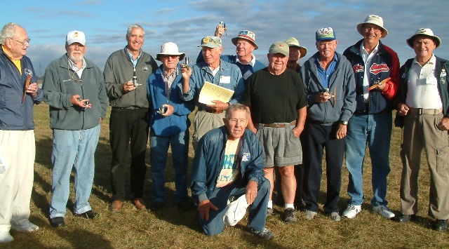
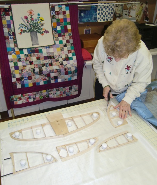
At the 2010 SAM Champs RC CD Don Bekins, SAM President Ed Hamler and Brown Jr. aficionado Jim Hainen sponsored revised Brown Jr events with the results that over 20 people participated in Limited Engine Run and Texaco events. The basic changes to the "Rule Book" events were, any Antique model is eligible, including pylon designs, no wing span rule and you could fly both events with the same model. Here are some of the competitors with their engine winnings donated by Jim Hainen.
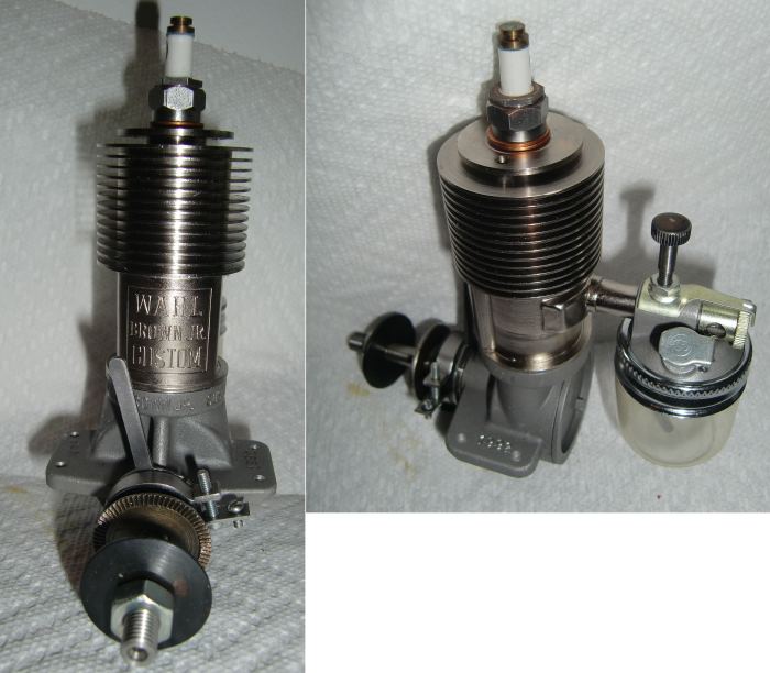
I have asked if these rules will be used in the 2011 Champs indicating I would acquire a Brown Jr. and compete if they do. Well, having made the offer Don Bekins offered me the Brown he won last year and just to make sure I would have what is needed I also bought a New In Box Wahl Brown Jr. replica.
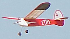
But I need a suitable airplane and since my build schedule is kinda full I wanted a simple but aerodynamically sound airplane. I selected the Ethy and bought a short kit and plan from Bob Holman. It arrived yesterday and I went to work immediately.
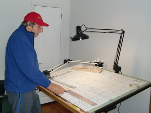
The first tasks were to consider the modifications necessary for efficient transportation; two piece wing and removable stab elements; separate fin and horizontal. Then I needed to make the working plans.
My building process ends up with the parts stuck to the plan. I don't like using saran wrap or similar plan protectors as I find it difficult to ensure the elements lay flat; particularly the wing trailing edge, which in many models, this one included, require you to shim the leading edge of the TE so as to get the right departure angle to the airfoil. So I make a set of build plans that can end up in the bin leaving a clean original plan. My process is to scan and or trace the parts with only the necessary lines. For instance, you can build a wing with only the leading edge and rib spacing shown on the plan. The ribs then position all the other parts. I have finished this process and now to clean off the bench and begin to select the balsa sheet and strip necessary to complete the build parts.
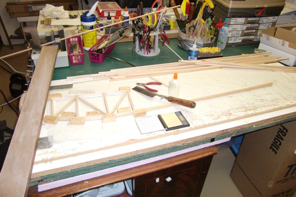
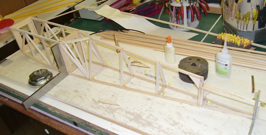
I finished that process and proceeded to layout the fuselage after weighing all my 1/4 inch square strips and selecting a matching set to begin. The Ethy fuselage is square at the front then aft of the wing it transitions to triangular; a bit of a challenge to build. Then the forward lower longerons must be bent a fair bit to conform to plan and I started by soaking the front ends of them in hot soapy water. That worked quite well and I quickly built the front end. You can see from the picture I held the parts in place with some 3/4 inch square blocks held to the ceiling tile building board with finishing nails. I used yellow wood glue for this stage and while it set and the wood dried from the bending process I tackled another task that is not time consuming to accomplish but it must dry over night; making the laminated leading edges for the horizontal and vertical stab.
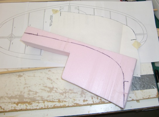
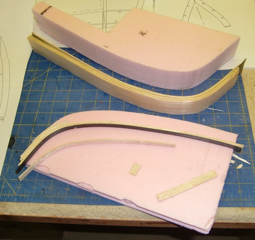
The process I use is to cut a pink foam mandrel with overhang at each end. In this case I used the softest 1/16 inch strip and thinned yellow glue. I also slipped a layer of graphite between the two innermost layers so as to add some stiffness.
For the horizontal I made the strips more than twice as wide as needed as I plan to slice the finished part down the middle to yield two identical (?) parts. The parts are held to the mandrel with masking tape drawn tight as you successively add the strips and move from one end to the other. One important point is you must mark the "end of part" on the mandrel to aid in cutting to final length.

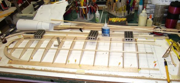
So after dinner I was able to remove the fuselage sides from the plan, sand the outer surfaces and then separate the two sides ready for the next step; building the aft end. To help jig the alignment I copied the cross section drawings from the plan and pasted them on to a cardboard form. I cut them so as to straddle the crutch and align the upper member.
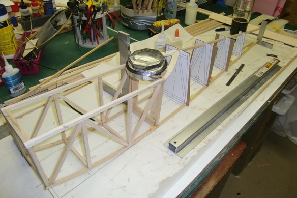
Then I added the 1/4 square framing, removing the mandrels as I went along, all the time checking for square. I finished the basic framing as shown here. For this part I used thin CA for most of the gluing. this is because you are kinda building in the air half the time and need the first part in place before you cut the next. Well, it seems to be ok although I am concerned that when I add the 1/16 inch sheeting to the whole thing it will be real easy to turn this into a banana. So I think tomorrow I will add some diagonals while I can still check square and tweak it if necessary.
31st January
I opened the laminated parts this morning and found I had made some mistakes. It has been a long time since I did one of these and I forgot to put any kind of release agent between the part and mandrel. Well the glue is not supposed to be on that surface but it is a very messy job and invariably some gets in. The horizontal stab parts were ok but the fin leading edge inner balsa layer separated. But it is an easy fix to repair it. Interestingly enough it seems the original Ethy had laminated stab outlines. The Bob Holman kit contains mostly sheet parts with just the end of the inner portion shown as laminated. Had I known I would have laminated the whole thing.
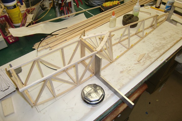
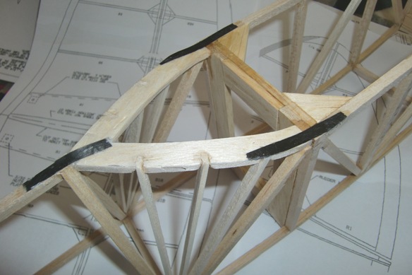
One thing that bothers me with many Old Timers (and some new timers too) is the poor structural design. It is not uncommon to see major load paths end with a but joint glued to another part. And worse, sometimes they are glued to another part such that the load is in the cross grain direction, which is significantly weaker than along the grain. So it is with the Ethy. The main longerons run the length of the fuselage but the upper longeron but joins into another shaped sheet part which in turn is but joined into the cross grain direction of the fuselage uprights. I deal with these issues with the addition of a structural strap across the joint. Here the strap is a piece of uni directional graphite.
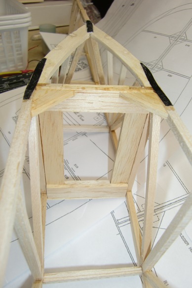
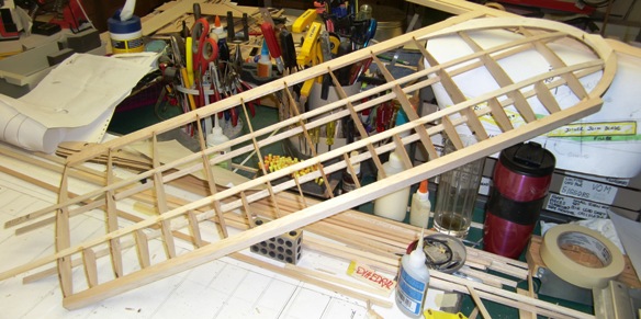
The Ethy design does not include bulkheads aft of the forward surface but with durability and construction alignment in mind I added two. Note the construction of these bulkheads. I can't remember where I got the idea but I do remember OFB Mick Harris uses this technique. You make the bulkhead from four wide strips overlapped at the corners. This yields three advantages; it is easy to make them truly square, they are stronger because the grain runs in the right direction all around and the glue joint is of sufficient area as to be very strong, and finally it is the economical use of material; strip with no waste.
Despite my better efforts the forward box was not quite true so I tweaked it. One of the diagonal glue joints was lose so I took the opportunity to increase the length of the member so as to twist the structure in the right direction. I then jacked it to just beyond true and added gussets in the corners of the bay under the wing. these are also a good structural element and made the final part "good enough" ( I don't make museum pieces, in case you haven't noticed; no excuses!).
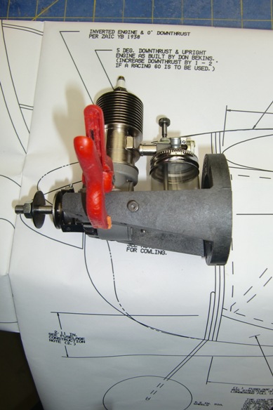
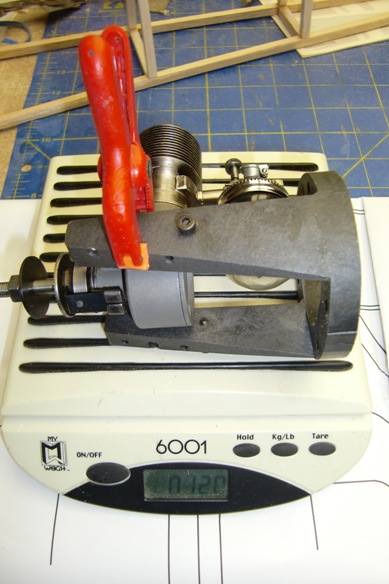
As the parts take shape and I begin to think about the internals I realized it is time to start analyzing the weight and balance, particularly the balance as this will not be an electric model with a heavy battery to move around to get the right CG. So I need to estimate the best place fror the servos, Rx and ignition parts. I do this by making a spradsheet of the weight and balance from an assembly of all the parts. I start by inserting all the known weights and part CGs then estimating the bits that don't yet exist. As the parts are built I update the analyisis and relocate parts that have not yet been fixed. So time to start weighing things. First I need to know what engine mount to use and it seems the Dave Brown 90xx unit I use in the Bomber is just right, so now I know where the engine will fit and what it weighs.
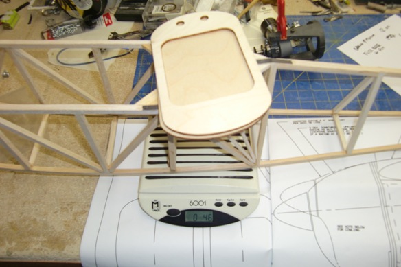
Next the fuselage together with the ply front formers from the kit. You weigh the part then hang it to determine the CG. One reason to start this now is it will be hard to change the part locations once the fuselage is sheeted.
Here is the Weight and Balance Spreadsheet. Looks tail heavy right now.
| Model | Ethy Brown Jr. | |||||||||
| CG inches | -6.06 | Not Weighed | ||||||||
| Chord | 11 | * from LE | CG % | -0.55 | Weighed less covering | |||||
| Target CG Location | 5 | Weight | 59.7 | Weighed True Complete | ||||||
| Wing Area | 750 | Wing Loading | 11.5 | |||||||
| Weight at 8 oz | 41.7 | |||||||||
| Weight | Location* | Moment | Comments | |||||||
| Airframe | ||||||||||
| Fuselage less sheeting and details | 4 | -8.00 | -32.00 | |||||||
| Fuselage sheeting and covering | 6 | -12.00 | -72.00 | |||||||
| Cowl | 2 | 2.00 | 4.00 | |||||||
| Empenage | 6 | -33.00 | -198.00 | |||||||
| L/G | 5 | 1.00 | 5.00 | |||||||
| Wing | 9.7 | -5.00 | -48.50 | |||||||
| Airframe Sub total. | 32.7 | 0.00 | ||||||||
| Propulsion | 0.00 | |||||||||
| Motor | 12 | 3.00 | 36.00 | 13.5 | ||||||
| Prop | 2 | 4 | 8.00 | |||||||
| Spinner | 0.00 | |||||||||
| Ignition system box | 5 | -2.00 | ||||||||
| 0 | 0.00 | |||||||||
| Propulsion Sub total. | 19 | 0.00 | ||||||||
| Systems | 0.00 | |||||||||
| Servos | 3 | -2.00 | -6.00 | |||||||
| Pushrods | 2 | -23.00 | -46.00 | |||||||
| Rx | 1 | -4.00 | -4.00 | |||||||
| Rx battery | 2 | -4.00 | -8.00 | |||||||
| 0.00 | ||||||||||
| 0.00 | ||||||||||
| Systems Sub total. | 8 | |||||||||
| Ballast | 0 | 0 | 0.00 | |||||||
| Total Weight | 59.7 | 59.7 | -361.50 | |||||||
| CG inches | -6.06 | |||||||||
| CG % | -0.55 | |||||||||
Now to start the empenage. I have cut the laminated leading edge into two pieces with about the right height, leaving some meat to sand to shape. So far it looks ok.
Oh, just a picture to show how I hang sanding bars, yardsticks, covering gun, dremel etc. to the side of the two-sided workbench.
February 1
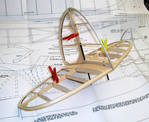
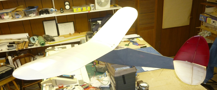
Finished the basic structure of the horizontal stab today. Made the mods necessary to incorporate my hold down method. Here you see some additional ribs in the center section. When the part is finished I will drill a 1/4 inch hole where the center rib is interrupted. This will be the primary hold down. The fin will have two extended spars that will project through the stab and the fuselage mounting plate to align both parts.
Here is the "finished" structure with all the elements sanded to fit, well, first cut. It is a bit of a brick outhouse and weighs 1.7 ounces as you see it. Tomorrow the fin and rudder.
February 2nd
Finished framing up the stab and attaching the locating graphite dowels. It weighs almost 3 oz.
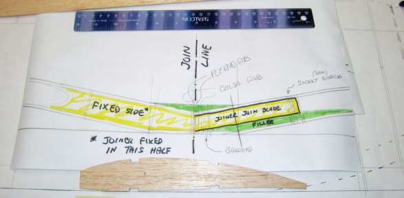
Now for the wing but first I had to figure out how I will make it two pieces and join it. I was taken with the nylon wing hold down approach on the Holman (Jim O'Reilly?) plan. I am tired of using rubber bands and this seemed neat except it was for a one piece wing. furthermore, like many Old Timers this wing has a flat center section over the fuselage, so where do you put the break? Where do you put the hold down screws and what does the joiner look like. I finally decided to break the wing right on the centerline. This means that each panel has one half of the center piece but that is ok, just makes the build a bit more difficult. Also the joiner configuration is problematic but I figure out how to incorporate a flat blade joiner that is fixed to one half ~ no need to make it more complicated than necessary and fitting blades into sockets is a pain. This way I will only have to do one side. Here is a sketch of the joint.
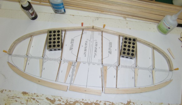
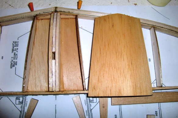
Ok, now I can lay out the wing structure. I know I must make the spars overhang the center part for trimming later. Here is the basic wing structure with LE, TE, Ribs and upper spar caps. Both the LE and TE required shims. The LE to raise it up to the right level and the leading edge of the TE to give it the right angle. I determined the size and placement of the shims by drawing a line depicting the building board under the rib. You are looking for how the LE and TE sit on the board to achieve the correct placement of these parts. I decided to make the upper forward spar cap from pine or spruce as this is the most highly loaded part, however I scarfed a balsa extension to the outer portion because the loads are much lower and I needed to bend it into the tip.
Having done this side I removed it from the board then laid it back upside down. First so the forward spar lay flat on the board whereupon I attached the lower spar cap. However, you must first make sure the spar it a good fit in the rib notch. In this case the spars were marginally thicker than the notch so I sanded the notch deeper using a finger nail sanding board. You can buy them by the bunch. I find them quite useful, in this case because you can cut them to the correct width (don't use any of your good tools to cut sandpaper!). Her is the basic structural part. Some material will be removed in shaping and other material added for the spar shear webs and to form the joiner socket. this part weighs just under 4 ounces ~ another heavy part!
5th February
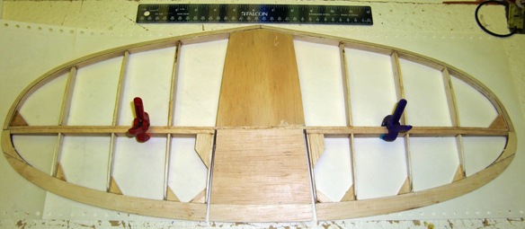
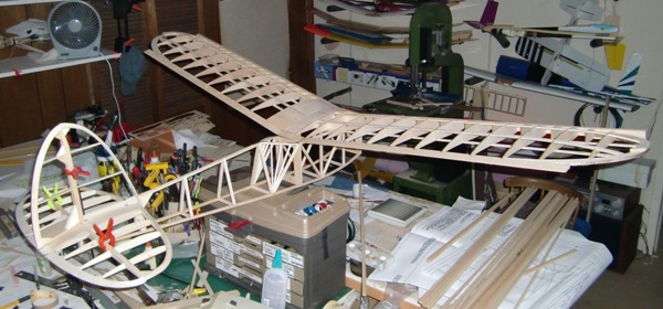
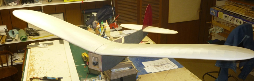
I built the second wing then spend a day or so building the joiners for the two piece wing. The joiners are made from pine block sawed to about 3/16 inch width then scarfed in the center to match the shape of the center section and the dihedral; the grain runs in the right direction and the scarf is reinforced across the joint by 1/32 inch ply on each side. I made the joiner to fix on one side and plug into sockets on the other. In each case the joiner interfaces with the spar caps. Here is the complete wing awaiting the sheeting of the second half inner portion and the shear webs.
Now I have to waste time fixing a hard drive corruption on my main computer. I have backups but need to fix the drive before moving forward.
I did manage to fix the computer after wasting three days but by then Mick had received an order from SIG for some Koverall, the covering material we agreed to use for our next models. For me this was because the Ethy is an Antique and I wanted to make it look so, and also it will be primarily a gas model and I didn't want to fiddle with the Doculam painting. Come to think of it, I have to fiddle with the Koverall painting. Anyway, I had finished the airframe 98% and it was ready to cover so I had my Fiber Artist wife cut the covering to right sized pieces. (actually I could of cut them but my work surfaces are more cluttered than hers and she doesn't have any balsa dust!
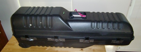
But now I had run out of time as I needed to figure out how to put everything in the golf bag; airframe, engines, motors, etc.
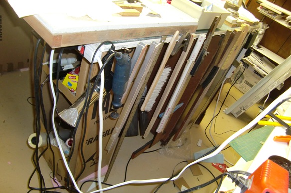
I decided to put all the heavy stuff in a plastic box and lash that to some fittings and bungees to keep it in place, leaving space for the airframe. I made some admonition notices alerting the friendly TSA agents what was there and how to put things back. I get about 75% TSA hits when they don't see any golf clubs in the X-Ray machine and always worry about them breaking stuff.
Anyway, the flights to Las Vegas and on to Burbank went fine and at least the golf bag arrived. The suitcase came later; funny, it is usually the other way round. So with trepidation I opened the case.

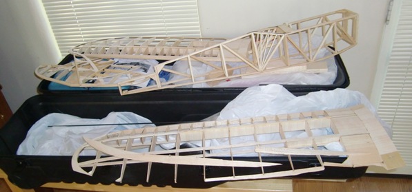
But there was some damage, almost certainly due to my packing job. There had been no TSA examination (they leave a ticket).
But now it is repaired and on to the next steps in construction; Sub fin, fuselage sheeting, front bulkhead, servos after a better weight and balance measurement, landing gear and cowling. And of course the covering. Should cover the empennage before doing the weight and balance.
Somewhere along the line Mike Myers and I will do some engine running up at Peenamunde, the test site in the draw behind his Glendale mountain house. Oh, I received the Brown Jr. from Don Bekins and decided to go with that and preserve the Wahl replica for now.
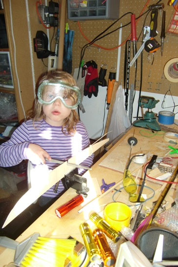
At least I have some help out here.
So I spent the time in SoCal continuing the build and covering, installing the servos etc. but the weight had crept up to an unacceptable level, at least, unacceptable from a competitive performance point of view. The projection was for it to be eleven ounces overweight. Anyway, I again packed it for shipping back to Pennsylvania and this time there was only minor damage to the sub-fin which had separated from the fuselage; an easy fix.
But there it sits, just needing the engine installation then fairings and landing gear to complete, but I have lost the drive to complete it now.
Dave Harding