Page 1 / Page 2 / page 3 /Page 4 / Page 5 / Page 6 / Page 7 /Page 8 / Page 9
Engine selection for Classic Texaco event
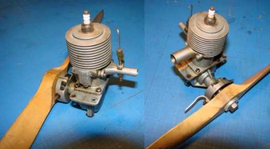
Forster 99 purchase
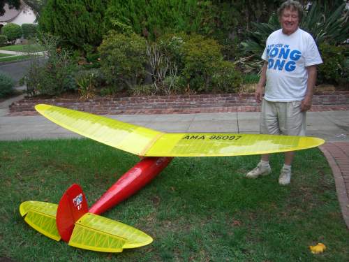
Goldberg Valkyrie, a present with the Forster
Wing spar construction
Wing spar joiner construction
Wing spar-joiner structural test
Joiner failure forensics
Joiner redesign and fabrication
Wing spar completion
Wing construction
March 15th 2008
After a wonderful Champs and a five month trip to SoCal dealing with my daughter's new baby and kitchen project, I am back in Pennsylvania and ready to start on completion of the Giant. In the intervening time I did some research on a suitable engine for Classic Texaco. The Ohlsson 60 seemed to have insufficient power for the 12 pound plane so after some consultations I settled on a Forster 99. SAM president and flying/eating SoCal buddy Mike Myers offered to lend me his new-in-box RJL replica, an offer I readily accepted. Then when musing about how to break-in such a fine piece of equipment Mike had me talk with Sal Taibi, a master with these engines. Sal said they are very hard to start initially because the rings don't fit too well but after a suitable break-in they start first flick. Concerned about a significant break-in effort in my suburban Philadelphia home I began to wonder if I could acquire a well used one. Having put the word out I learned that Don Bekins was willing to part with his own engine and a deal was quickly made.
Following our agreement Don asked if I planned to drive to the2007 Las Vegas Champs and when I told him my plan was to rent a van and drive from SoCal he made me another offer; a full-sized Goldberg Valkyrie in a shipping box. The very model he flew with his Forster. How could I refuse, so even though I rode with Dale Tower in his van we still executed the deal.
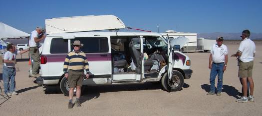
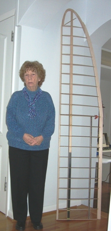
Here is Dale with the Valkyrie in South Pasadena on daughter Judy's back lawn.
So now I need a Forster on the East Coast and on the West Coast. Maybe Mike will let me borrow his for the Valkyrie. But my Giant powerplant for Classic Texaco is well satisfied and I can get on with finishing the construction.
When I left it the next task was to build the wing spars and test them before making the wing assembly. Taking some time to reacquaint myself with the design and in particular the details of the structure I discovered that I had made a fundamental error in calculating the spar loads. It was all to do with the spreadsheet approach to adding the incremental loads along the spar from tip to root.
I had planned to design the structure for a full capability aerodynamic pull-out at 60 mph. This would result in a pull out of 120 pounds or 12 g with a ten pound airplane and 10 g with a twelve pound plane. However, when I corrected the calculations the most I could stand with the general structure I had already designed was less than 6g, a full capability pull-out at only 45 mph. Now of course I could limit the control authority so as to stay within these loads at higher speeds and I will probably do that but in the meantime the structure I had begun to build was somewhat inadequate.
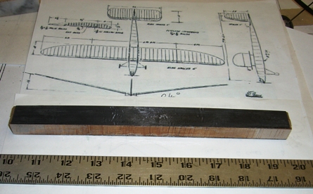
But I had concerns about this structure from the beginning and one way to alleviate the concerns is to test the parts before committing them to assembly, and this is what I have done, but not before reassessing the structural design and making some changes. The specific changes are a more extensive spanwise and thicker ply shear webs and an addition of two plies of graphite to the outside of the spar over the inner 26 inches. The upper spruce spar and lower hard balsa spar constructed previously already had one layer sandwiched in the center of each. See their construction back on page 2.
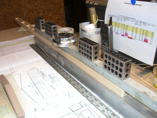
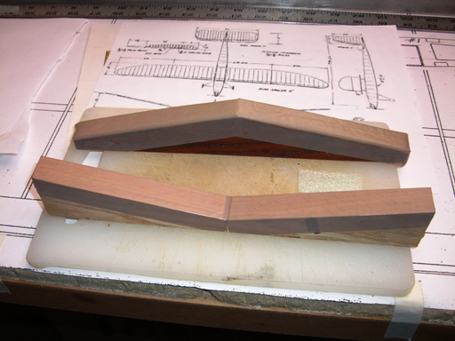
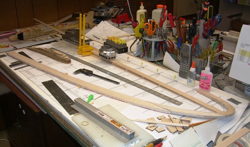
I started by assembling the left-hand inner spar, then added the shear web to one side. Here is the method I used to tool this operation. I have two long square section aluminum bars that serve as the facing tool surfaces. Sundry weights hold the assembly under pressure during curing. With only one side shear web attached I had access to the sockets into which the joiners would nest. This allowed me to make a tight fitting assembly without having to probe down into the socket into a blind end.
Now my concerns are for the whole wing structure assembly so I need to build all the parts that will be tested including the joiners between the center panels and center to tip.
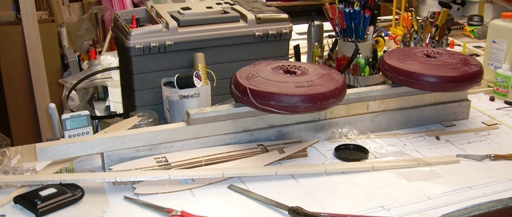
The joiners are made from a suitable number of graphite plies glued to top and bottom of end-grain balsa cores. The graphite cap strips were pre-made using a wood form shown here.
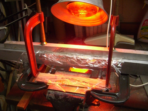
I applied the epoxy between each ply and wrapped the assembly in saran wrap. This was then placed in the tool and clamped in a vice.
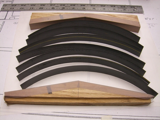
I found the strong epoxy I had on hand required heat curing so I rigged up such a setup. Then proceeded to lay up the caps for the outboard spar joiner, also on the aluminum bars. These were cured simultaneously.
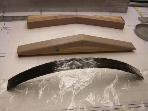
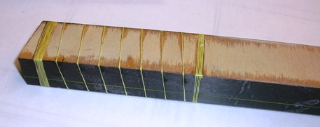
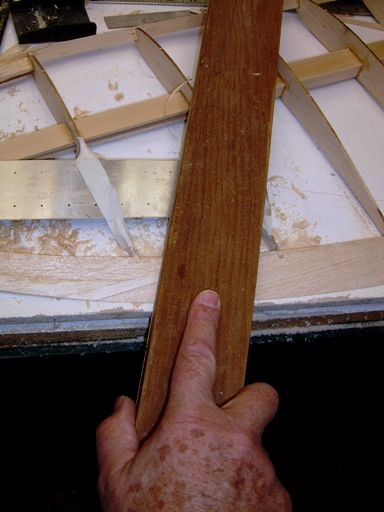
A second set was made to complete the graphite parts required. Here is an outboard wing joiner, note the end-grain balsa core.
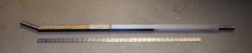
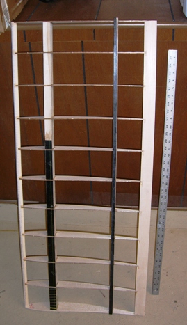
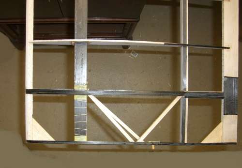
And here is the complete spar assembly with both center and outboard joiners. Note the change in spruce ply shear webs outboard and the graphite reinforcement on the bottom surface. This assembly is ready to test.
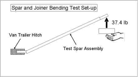
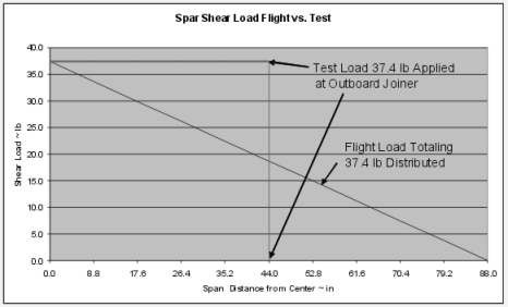
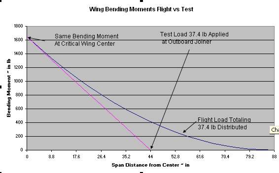
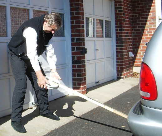
There are issues with test methods. Unless you test the whole thing in its intended environment there are differences between test and real results. My concern with this assembly is the bending strength along the whole spar and into both joiners. Obviously in the real world this part is assembled into a complete wing which sees lift loads along its length, resulting in a bending moment and shear load distribution. I plan to test it by fixing the root end joiner into a custom made socket, plugged into the trailer hitch of my van. I will then apply a lift load to the outboard joiner via a bathroom "dynamometer", hence measuring the applied loads. Now this will result in a different distribution of loads along the spar when compared to the distributed loads in flight. Also, the fixation of the joiner is somewhat different than achieved by its attachment to the other wing. But since I am concerned primarily about the highest loads, those that occur at the wing root, I will apply a load that results in the same root bending moment as the flight load case.
Sunday 23rd March, 2008
Now to the test.
Oops, bad news for the design, good news for the Giant. Planning to apply a proof load of 37 pounds the mid span joiner failed at 10 pounds.
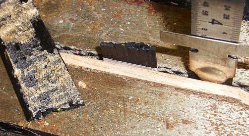
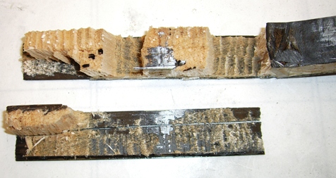 The failure occurred initially in the balsa core; a classic shear failure. The secondary failure was the compression side spar cap. The failed cap part shown in the picture above shows a second failure, a longitudinal split. This was caused during removal of the core material so the core-cap joint could be examined. The joints were good. How could this failure occur at such low loads; only about 25% of the design load?
With some thinking about the test setup and some sanity consultations with Mick Harris I concluded it was due to the test setup, and in fact was a valid failure for the Giant application too. I had made a mistake by designing the joiner and spar as a through spar, which it is not. Examining the true design and loading yields much higher loads in the joiner. Here are the conditions of the test at the failure load.
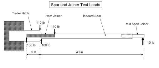 Since the parts are discontinuous the moments must be reacted in the sockets; joiner in the spar and joiner in the hitch socket. The failure at 10 pounds applied load at 40 inches was reacted over a four inch socket. This required a 110 pound shear load to react the moment. So, the shear stress in the joiner core was 230 psi whereas my data base suggests 180 psi capability. So the part performed well, it was just designed poorly. Clearly to react the 37 pound design load I will need a core material with a shear strength four times or about 1000 psi. Spruce ply is good for 900 pounds; good enough.
But what about the failure of the joiner graphite cap? This stuff is supposed to be very strong. Why did it fail. Was there something flawed about the laminate assembly? So I tested this part too, using the piece that separated from the spar cap on failure.
The failure face looks like it should for a bending failure.
The bending strength from this test is 160, 000 psi a good number. So why did the cap fail in the spar and joiner test? Apparently, when the core failed the loads were reacted just by the upper cap, which failed in shear and the shear strength of a pure uni laminate is the strength of the epoxy ` about 3000 psi, or a 72 pound local load.
So I built a new joiner with a ply core. The core weighs 18 grams and the completed joiner 2.2 oz.
But what about the root end of the inboard spar? It too must react these same loads. The shear stresses in the ply shear webs and in the glue joint between the web and the balsa/spruce/ graphite caps are within allowable strength, but there is a belt and suspenders addition that I and others do with joined wing spars and sockets, and that is to bind the socket joint with strong thread.
Since I was on a roll, I started by testing the Kevlar thread. It is good for 25 pounds. So the winding at the root and tip end of the joiner socket contains sufficient winds to react the loads.
Now for the "final" test. It went to 25 pounds when it started to make a few clicks and I lost my nerve and declared victory. It is normal for structures to make distress sounds as they approach the limit. Total failure may be quite a bit beyond the point of initial indications so that is my justification and I am sticking to it. But I will add a few more turns of Kevlar to the outboard end of the inner joiner socket after I slide on the ribs.
Now to move on and build the wings.
Tuesday 25th March
Finished the basic wing structure for the LH inboard panel.
 I decided to add graphite strips to top and bottom of the aft spar to help hold the trailing edge straight and to increase the torsional stiffness of the wing. It seems to work as it is very stiff even without the covering. Now to make the spar and build the RH inner panel.
Wednesday 26th March
Continued the build up of the RH inner spar and bonded the shear webs then the graphite reinforcement. Tomorrow it will be ready for the buildup with ribs, TE and LE.
While the various glue steps cured or set, I use CA, epoxy and white glue as appropriate to speed and strength, I began the details of the RH outboard wing panel. I started with the spar, as with the inboard panels, but this one is tapered in thickness. Jim O'Reilly had laid out the CAD design for the ribs to contain this large box spar and Bob Holman had dutifully cut them perfectly. The spar is made up from an upper cap of spruce, about 1 x 1/8th and the lower from balsa of the same dimensions. I measured the depth of the spar opening in each rib then figured the separation between the upper and lower cap. then I cut small "ribs" to nest between the spar caps as a means of holding the geometry while applying the shear webs. Actually, the inner few bays include a second layer of balsa cap strip to handle the root bending moment and to interface with the inner to outer joiner. Here is the spar assembly with the cap doublers being bonded to the caps and holding the desired geometry. this is a white glue step.
While the various glue steps cured I also cut the TE blanks from 3/8 inch stock and joined two of them. I also made two tips by laminating three layers of cast off rib material; that which remains once the rib is removed from the sheet. There is a lot of good wood there and I couldn't see it going to waste.
Tomorrow I should be able to assemble the RH inner and outer wing panels, but first I have to bind the inner spar and give it a proof load test.
Thursday 27th March, noon.
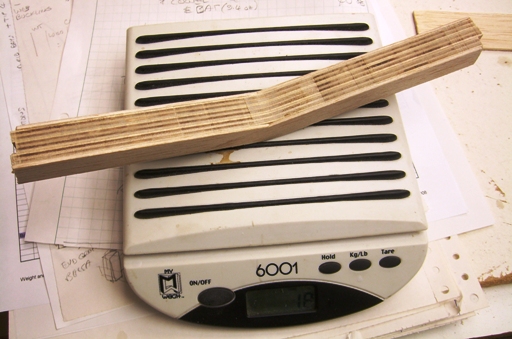
Here is the assembly of the inner wing panels. 26 ounces so far against an overall wing budget of 66 oz.
Back to the outer panels.
What a jig saw puzzle! I had measured the chord of the outboard elliptical tips and put them in a file for the rib burning. But now I come to align them there are errors such that they don't uniformly meet the TE. I suspect the plan is off as it is not a CAD drawing. Oh well, as long as I paint the completed model with some opaque color nobody will be able to see my patchwork structure. The assembly is largely glued together for the RH panel and I will lift it off the plan tomorrow morning. Meanwhile I have partly laid up the LH outer spar and glued together the TE and Tip parts so perhaps the second outer panel will go together quicker. Who knows, maybe I will have a complete wing structure by tomorrow night.
Friday March 28th
Here is the result of last nights efforts once the glue set overnight. Now to glue the LH outer spar so I can begin that assembly. Then start all the fiddly bits, and shaping.
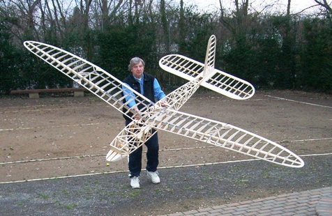
4 pm. OK, did the other outer panel and here is how it fits;

The wing as seen here weighs 42 ounces including joiners. I have been carrying a target for the complete wing of 66 ounces. This is a 20 sq ft wing so the covering will be 40 sq ft or about 4.5 sq yards. Covering of Mylar and silk may be as much as 3 ounces per sq yard so I will carry a bogy of 13 oz for the complete covering. then there will be other details so I will carry 16 ounces for the remaining wing elements, for a total expected wing weight of 58 ounces, or 8 ounces under target.
Probably have to spend the next two days working the details and shaping all the important bits, like the leading edge etc.
Saturday March 29th
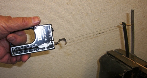
Only spend a little time on the Giant today. I started working on the job of blending the elements of the wing structure together. Here you will see the job of blending the trailing edge into the rib contours on both top and bottom surfaces. Note the thin steel rule protecting the upper rib surface as I blend the front of the TE to the back of the rib. I can't decide if I hate this job for all the sanding and dust, or love it because this is where the good aerodynamics stem from.
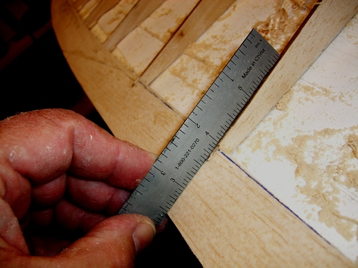
Why do I use ball point pens to mark the parts? There is no way I can remove that line! I told you I will need lots of opaque paint in the finish.
More tomorrow.
Thursday April 3rd
I continued the finishing of the wing structures for the last few days. There are a couple of techniques I use to get the desired contours. First I find that everything does not usually fit together perfectly so having shaped the basic parts I then fit, plane and sand them to shape. This frequently involves adding some shims either because the parts did not fit, or I shaved or sanded off too much!
Here I have added some shims to match the rib to the TE.
![]()
Now I shave and sand the shim to match both the rib and TE contours. I don't want that tell-tail wrinkle in the covering at these intersections.
![]()
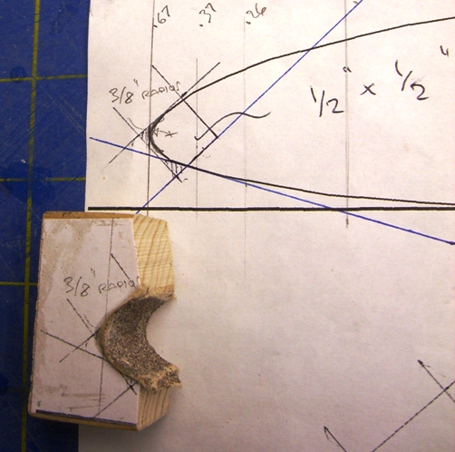
Next the leading edge. It is easy to sand the intersection between rib and leading edge but the rest of the contour is a little harder. On the bigger airplanes I have begun to use a shaped sanding block to achieve the final contour.
The block is cut from a piece of pine with a copy of the rib pasted to it. I add an offset to accommodate the thickness of the sandpaper then cut and finish the block before gluing in a piece of sandpaper.
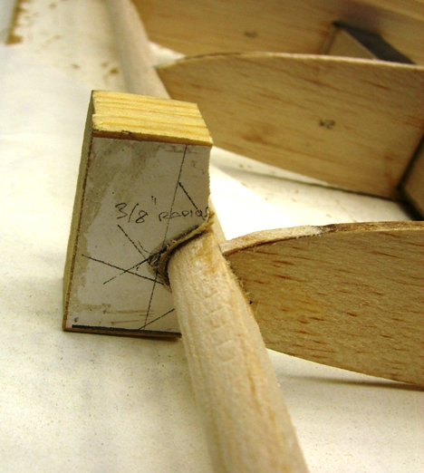
This step is now complete. In this picture note the shim on the upper surface of the rib. Guess I over sanded the first blend with a sanding bar and had to put back what I had removed.
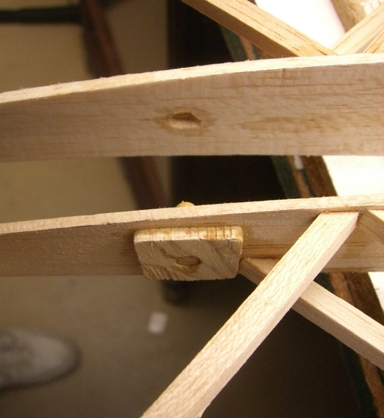
I added 1/4 inch dowel keys between the four wing panels. They are backed up with 1/8 inch lite ply on each rib. These act together with the joiners to ensure the sections will be aligned when assembled.
I think the wing structure is now complete and shaped. I will now inspect the joints and fix where necessary. I will also add some graphite cap strips to the rib surfaces where I think the spar has significantly weakened them. The spar is so big in much of the structure that the aft portion of the rib is largely supported by the glue joint between the rib and back of the spar. This is a tension joint and therefore quite weak. The failure mode is probably splitting the wood on the back of the spar; not good.
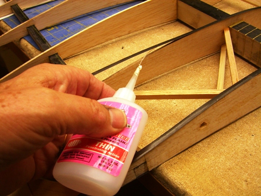
I apply the graphite cap strips with CA adhesive. I first attach it to one end then apply lengths of CA and rub the strip down with my fingers wrapped in plastic bags or saran wrap. Of course it is not a completely glue tight applicator and I am having some difficulty typing this with all the glue on my fingers. It is much harder chewing hard CA off your fingers than was Ambroid in the old days!
The wings are now essentially complete with just a little sanding of the graphite to finish.
Tomorrow I will start back on the fuselage and tail.
Yikes, I just realized I have not accommodated the wing to cabane mounting in the design. You don't just rubber band on a wing that is designed to a total lift load of almost 80 pounds. And if you did the hold-down loads between the wing and cabane would crush the structure somewhere unless you provided for it;
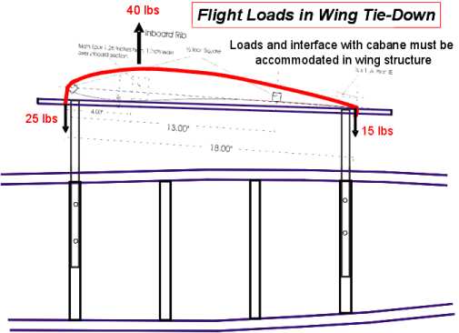
The first rib from the centerline is almost aligned with the cabane longitudinal, but of course you have to handle a wing that is knocked off square so I need to add some kind of extensions to the rib in that area. I am concerned with both the leading edge hold down at 25 pounds per side and then the trailing edge at about 15 pounds. I think I will add some false ribs to each side of the current rib then reinforce the whole thing with graphite.
The wing will actually sit on the bottom of the spar and the trailing edge, although I may make some kind of shaped pad to the cabane so it also rests on the leading edge. I will need to add a pad to the main spar to take it out to contour.
Here is a partial result of the solutions to this challenge. I added some extra rib material and graphite caps to the first outboard rib, the one that will almost sit on the cabane horizontal. I also added graphite to stiffen the TE to take the "rubber bands" or whatever provides the hold-down clamping force. Actually, I think I will make up some loops of strong tape with a fitting located just a few inches ahead of the TE. I will loop it over the front hold-down and then use the ubiquitous #64 bands to finish the attachment. More on this later.
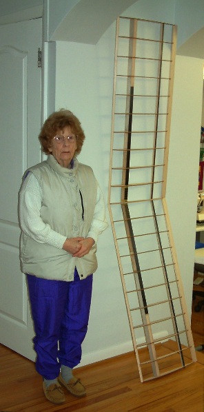
So, it has all come together, minus a few bits, like the cabane.
More tomorrow if I get time. Time for a new page;
Page 1 / Page 2 / page 3 /Page 4 / Page 5 / Page 6 / Page 7 / Page 8