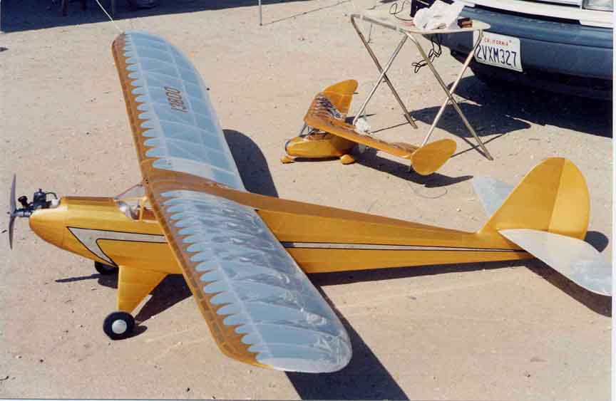
My Brown Jr. Ethy turned out to be very disappointing as it was headed to be 10 ounces overweight and maybe more, so I haven't finished it although it would not take much to do so. But I still want to compete in the Brown events at the Champs so I sorted through the eligible model lists and decided to build the Weather's Westerner. It seems to be an easy build and have promising aerodynamic characteristics. I found a plan on the internet;
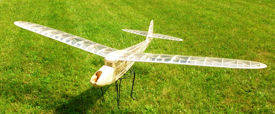
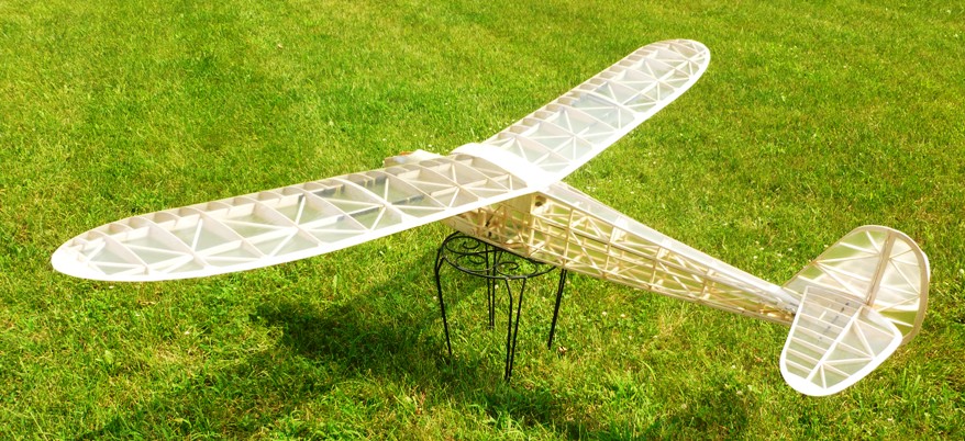
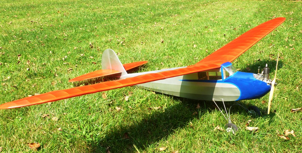
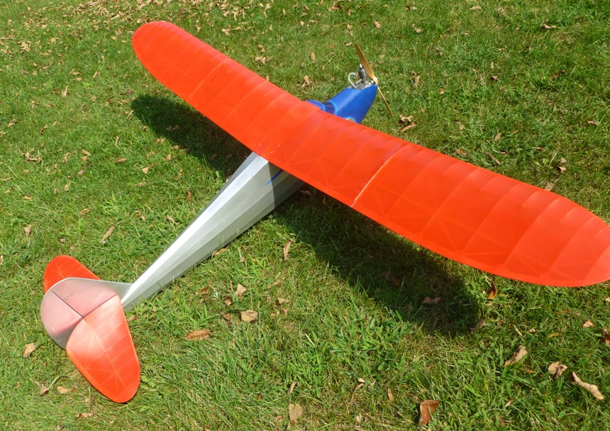
Here is one my friend Eut Tileston built.
The span is 96 inches and of course I want to transport the model so I plan to make the wing in three pieces, vice the two on the plan. Several reasons for this, first the joiner carries lower loads, second it is in a straight section so easier to get right and easier to construct. However, the Westerner spars are buried in the wing and only modestly sized so that complicates the joiner compared to the simple case with upper and lower spar elements where you can put the joiner in the middle.
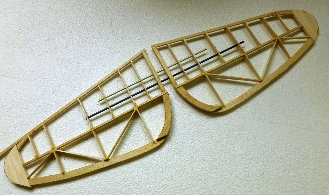
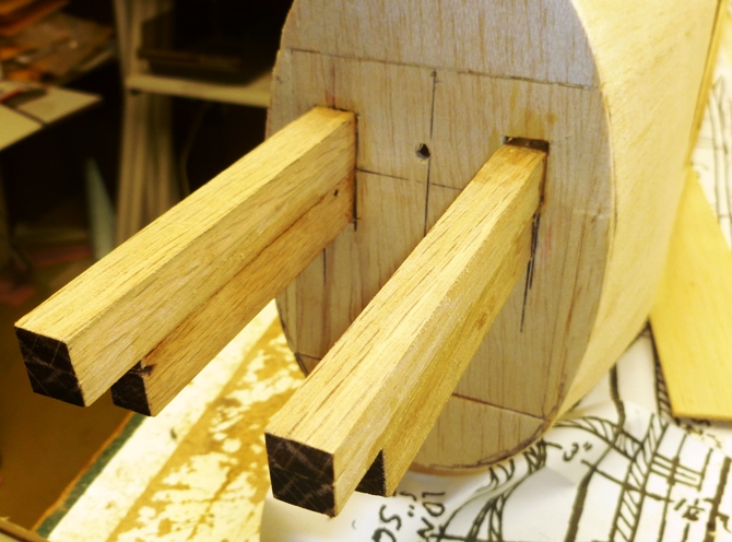
I settled on making the joiners as graphite "blades" the full height of the spar, glued in one side and pocketed in the other. The pocket is made by slitting the spar to accommodate the blade element then reinforcing the spar on the outside with a top and bottom closure to make it into a box. I plan to wrap them with kevlar thread at each end of the joiner location. Here are the forward and aft spars with the joiners already made.
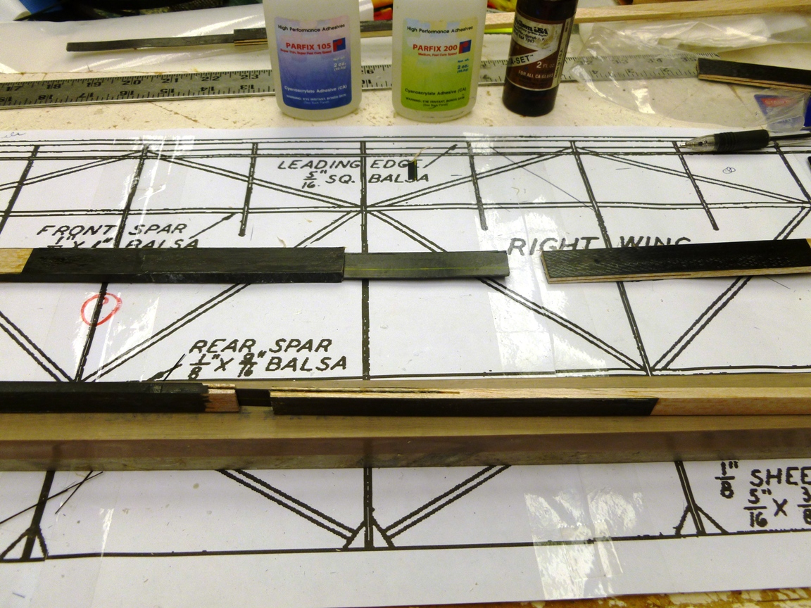
The upper spar in the picture is the forward spar and has the blade joiner trial fitted in the socket. The right hand half awaits the fitting and will accept the blade glued into place. The lower spar, the aft one, has the blade fitted in the socket and slightly withdrawn while the right hand end is being glued into place. Both spars elements are sitting on a rigid straight bar to maintain alignment during the gluing process.
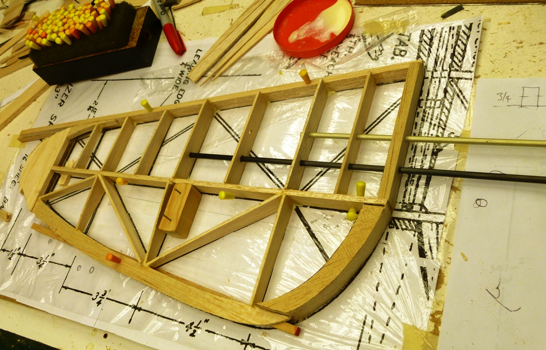
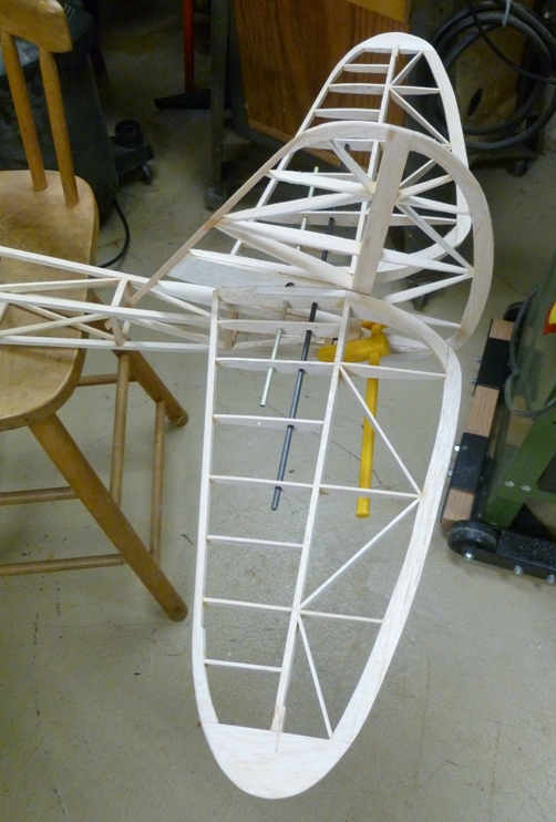
Here are both spars and joiners in place with the right hand wing construction.
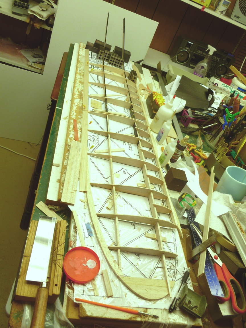
Note, the spar of the center wing includes both inboard halves and therefore also sets the dihedral.
Now to let the glue dry and make the other half tomorrow.
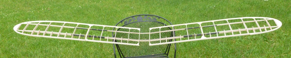
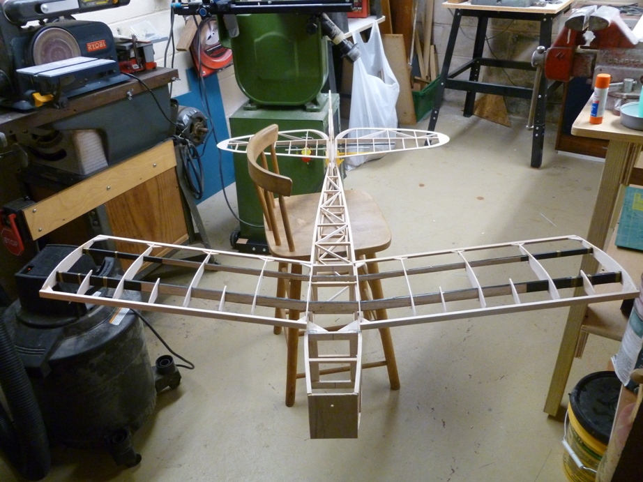
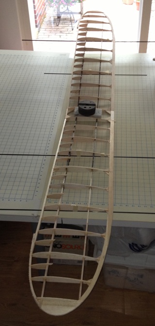
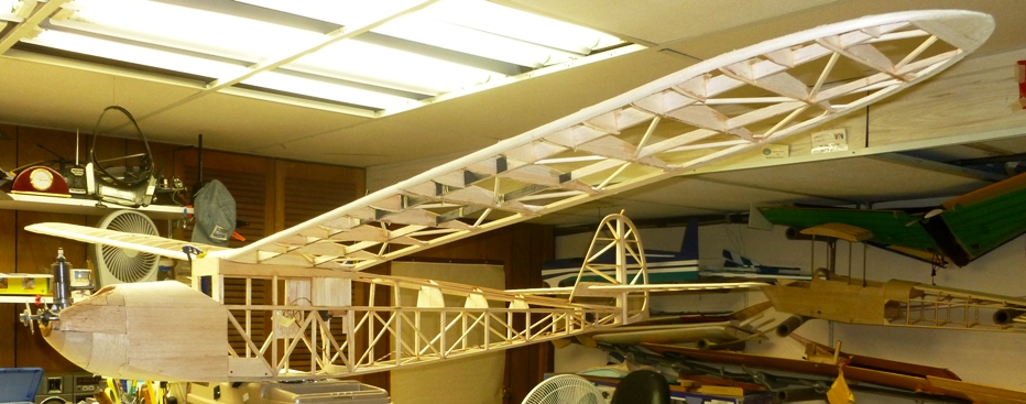
Here is the competed "bones" of the whole wing with joiners complete and most parts in place.
Began the frame up of the fuselage;
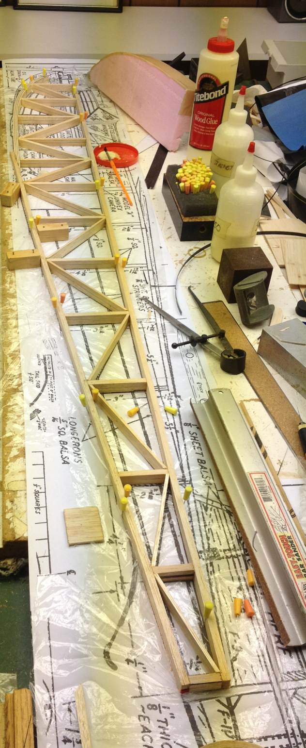
Decided to laminate the lower front longeron. The longerons are about 50 inches long so a joint was necessary and the lower longeron requires a significant bend at the front. Laminating is easy and fast so long as you allow for an overnight cure/drying time. I sandwiched two layers of uni graphite between the balsa elements. The front end of this model could see some high loads and vibrations so a little extra strength is a good thing. See the foam tool behind the structure. I cut the thick foam board to shape, including an extension beyond the "end of part" lines. In this case I wrapped it with teflon tape. Then I make the parts more than twice the width required. In this case I laid up a 3/4 inch wide stack of 1/16 inch balsa glued with thinned white or yellow glue then I use masking tape to lash the part to the mould. When it dries, usually overnight, so plan ahead, I then true one edge and mark and cut both sides from the single wide part. this way both hand parts are identical.
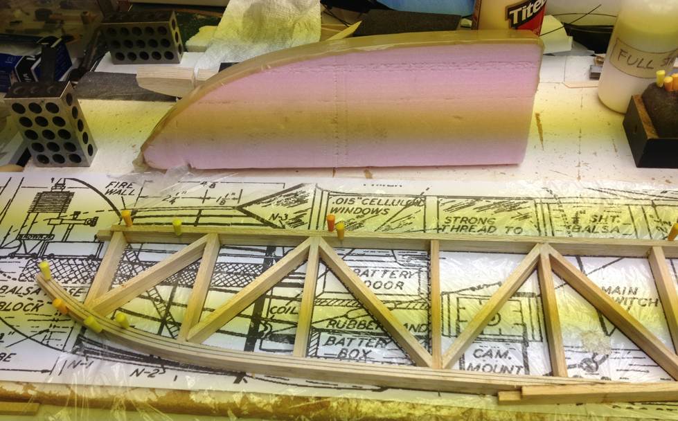
I think my iphone camera has some interference issues with the ton of fluorescent lights over my work bench, hence the yellow stripes.
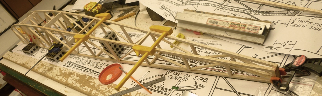
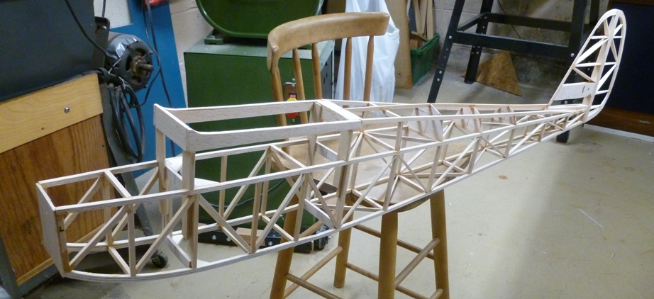
Popped the frames and squared them up. This is the basic fuselage absent the portion behind the "cabin". The top line is straight so it is easier to join both halves and square them up with this flat line on the building board.
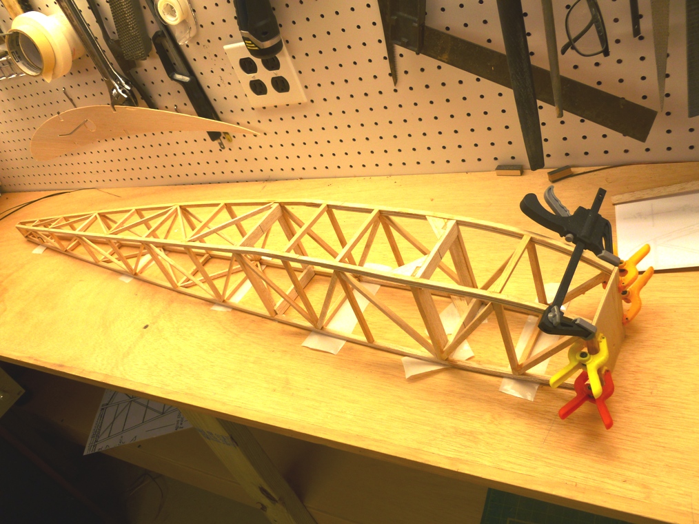
Now I have added the diagonals aft of the wing trailing edge. I will add the detail forward of this point when I figure out how I am going to mount the wing and landing gear, also the engine mounting.
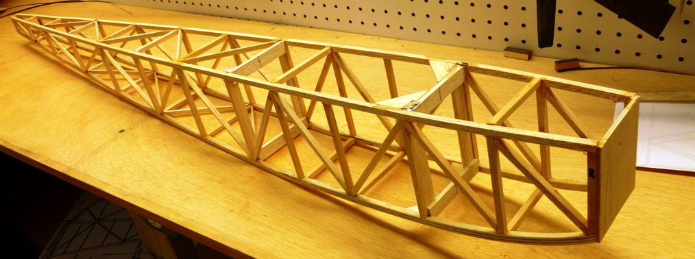
Here is that structure the right side up. Note my preferred style of basic formers. They have the grain running in the best direction on each side and you can make them really square. A great way to begin the process of joining the sides and keeping things true. (no bananas here.... I hope!)
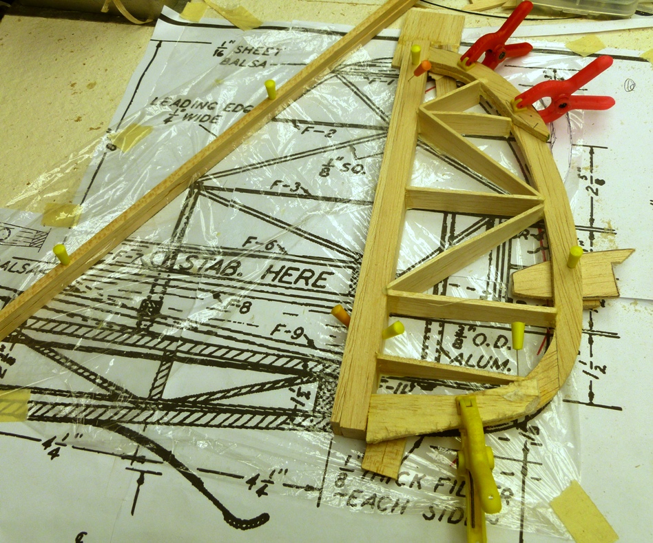
While waiting for the glue to dry, I am using Tightbond, I have started on the Horizontal stab. I have decided to make it an all flying horizontal. All my models are designed to be transported and one of the key features is a removable tail. The location of the horizontal on this model makes it a little more difficult to do it in my usual way so I decided to make the horizontal all flying, and therefore removable, and also make the fin and rudder as a removable piece separating above the horizontal location. Haven't designed that piece yet but the horizontal will be just like the one I did recently on the TU-ANT-25 Speed 400 Scale Duration, where the servo and mechanism are contained inside the tail and the horizontal stab halves just push in on a pivot tube and control tube as shown below.
The key to this approach is to precision drill the holes for the pivot and control tubes in the entire stack of ribs that contain them. The alignment is then controlled by the spar, as you see below. Of course, you drill the ribs for both halves at the same time so they mate perfectly together.
When the glue is dry, and it may already be there, I will lift the plan and oil the lines on the back side so I can read it when flipped to do the other half.
Here it is completed in the rough. Good deal of shaping required, but the parts fit!
Here is the start on the vertical. Fin rough finished, LE in place awaiting the fin structure including the horizontal control mechanism
More tomorrow.
Here is the completed tail clamped to the fuselage;
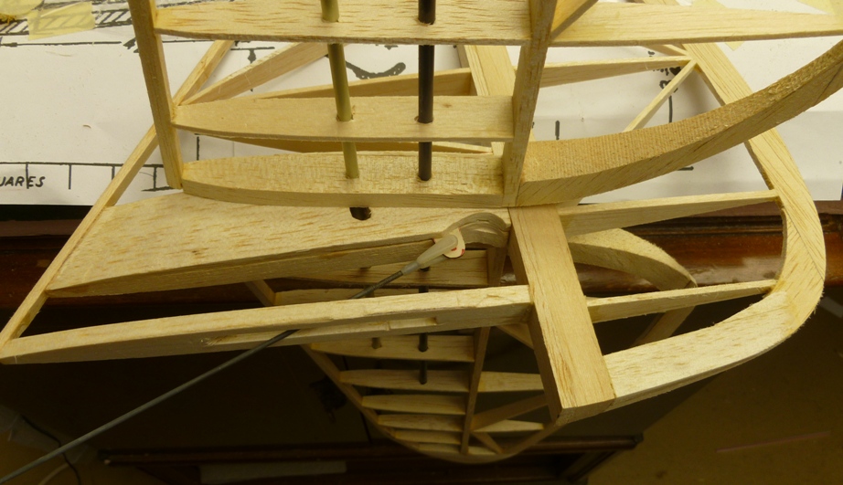
Note the flying horizontal mechanism in place ready for the servo and linkage. Well, alright, you can't see the mechanism but I will take another picture.
Here you go, a formica bellcrank is sandwiched in the thick rib. It pivots on a fixed bushing through which the stab pivot tube passes. It also contains a register hole for the stab control tube, the aluminum one forward of the pivot. A bellcrank arm extends below where it will interface with the servo push-rod. I haven't decided where to mount the servo yet, but it will probably locate forward and I will install an interface bellcrank at the base of the fin to change the motion from fore and aft along the fuselage to angled up to the stab bellcrank
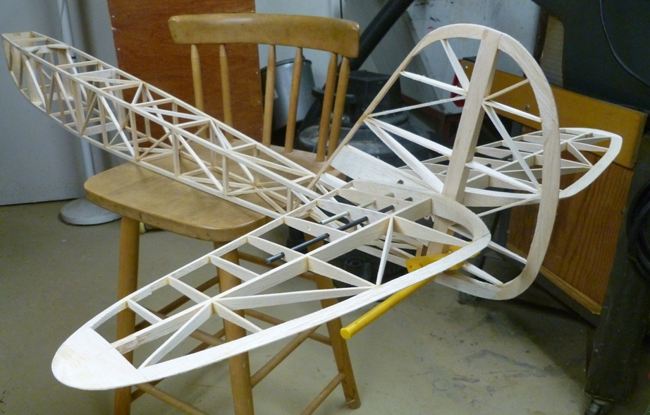
And some of the frame-up sitting on the fuselage bottom half, ~ no cabin top yet. That comes next, well, after I finish shaping the wings.
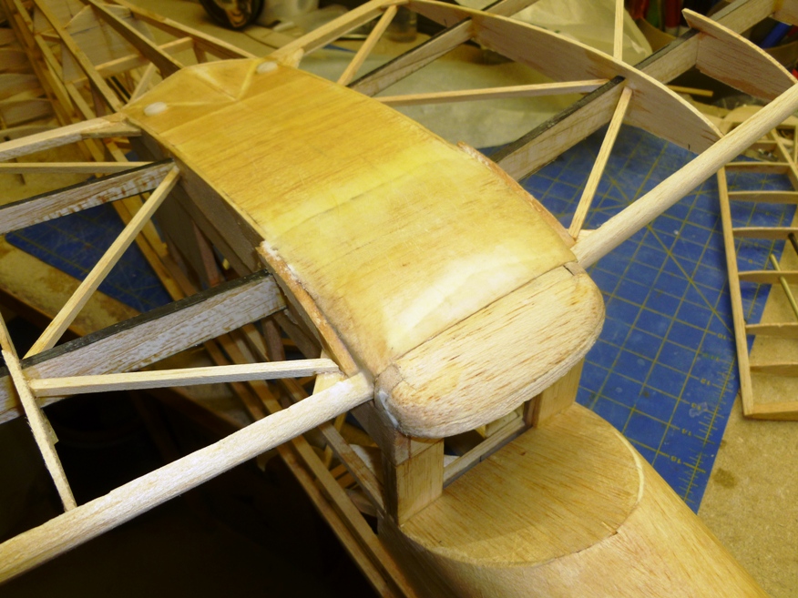
Added the wing mount at the cabin and the fairing behind it. Also fixed the fin in place.
The fairing is a little different from the plan design. The reason is I want to experiment with the wing incidence and the original design seems to have the wing fastened to the top of the cabin at a very low incidence; flat bottom of the airfoil horizontal. This would mean at the optimum glide condition the fuselage will be dragged around in a nose up attitude of several degrees causing unnecessary drag. So I have omitted the slight aft fuselage fairing portion that would sit on the after part of the wing and interface with the fuselage.
Once I get the model sorted I may go back and make a better wing attachment method, dowels and screws, and add the fairing extension over the wing.
Cut some engine mount beams from some old oak flooring boards and built up the structure. Want to mount the Brown Jr. and the Ohlsson 60, and of course an electric motor so I can fly the bloody thing from our field.
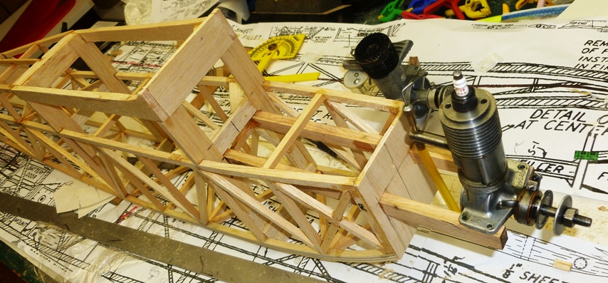
Now for the nose streamlining and shaping. The plan calls for a ton of very light stringers, but I may put the McCoy 60 in this puppy some day so a little extra stiffness is in order. My weight analysis suggests I have a little margin so I decided to sheet it. Done, but not yet sanded. I will do that after adding and shaping the nose blocks.
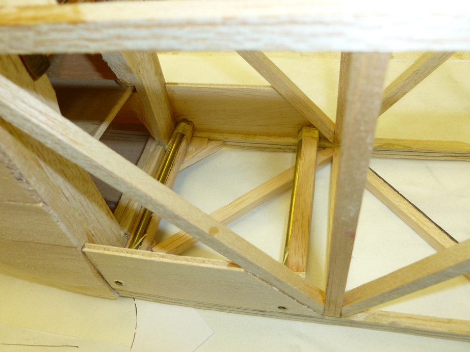
Next I made the landing gear mounts into the fuselage. All my airplanes are transportable so a removable landing gear is required. I shall make two separate landing gear halves; Right and Left hand with a connecting spreader bar below to add to the springing and hold them in place. The mounts include brass tubes into which the landing gear legs slide. These are lashed to oak bearers which in turn are glued into ply plates attached to the structure. The brass tubes extend into the plates so the primary landing loads are fed directly into the structure. The oak bearers handle the bending loads that occur cross-ship from the landing gear vertical loads. I have used this design on my Boehle Giant and it works just fine.
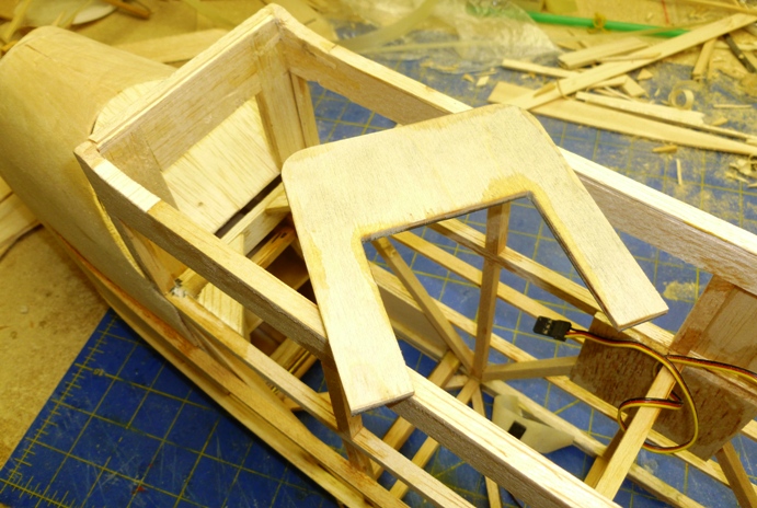
I am now dealing with the empennage controls. The question is where to put the servos. I can put them aft eliminating long pushrods with the fitting and weight implications, or I can mount them forward. I have decided that it depends on the projected CG. Can I stand fitting them aft? Here are the options, I started making the bellcrank direction changer for the forward servo mounting.
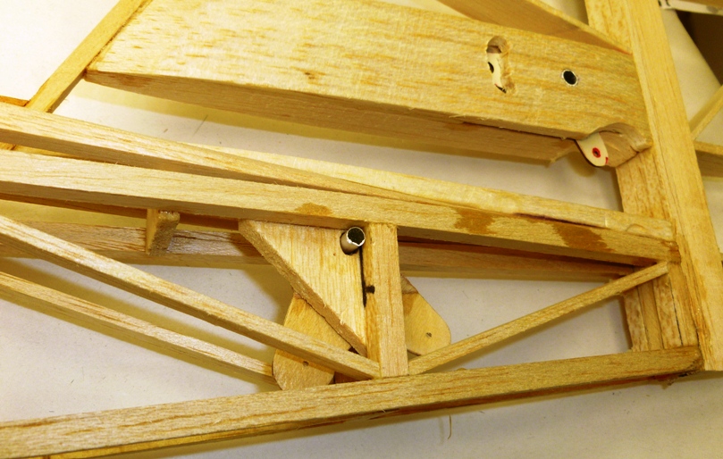
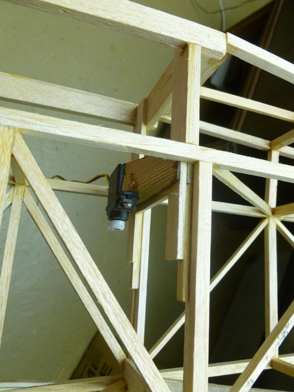
Then I explored the possible location for a direct acting servo. Note the pitch change bellcrank in the stab attachment shows the red hole for the input linkage.
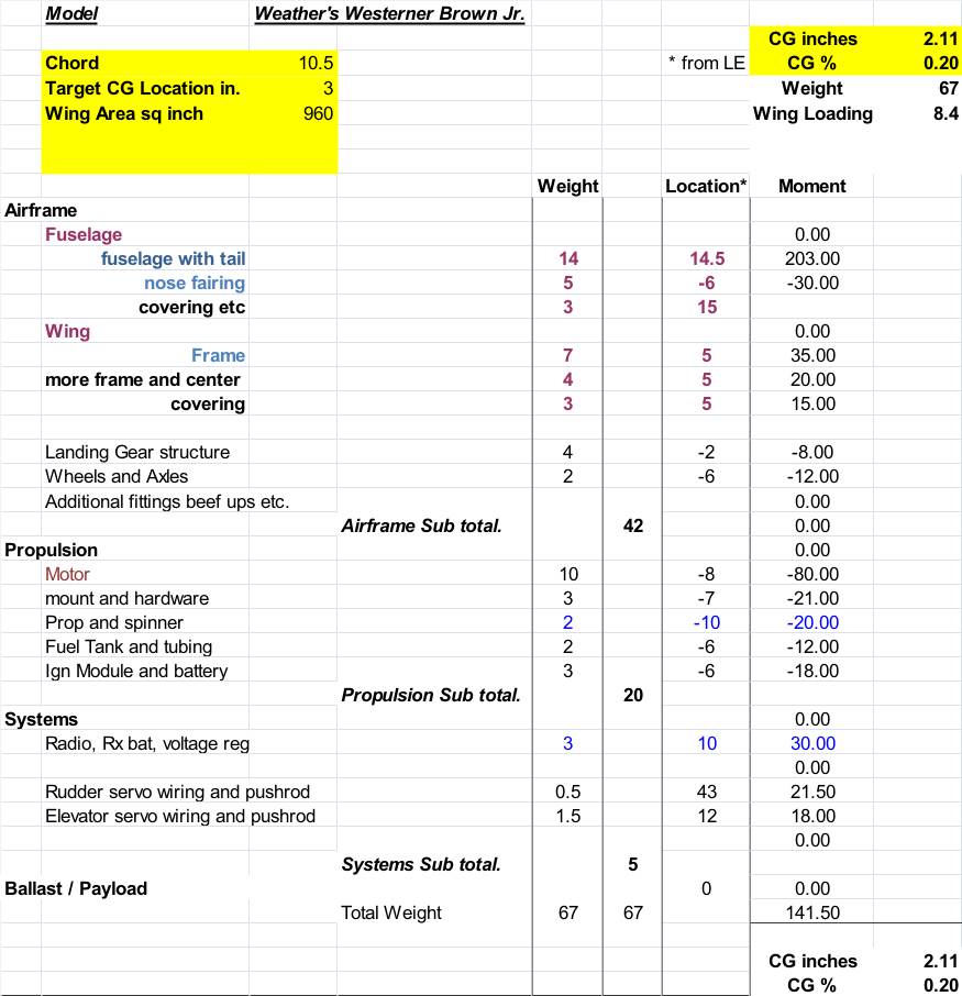
So here is the latest weight and balance analysis and estimate. Much of the airplane weight is now from elements that have been built and measured so the estimate is getting to be quite accurate and suggests an aft location of the servos is OK.
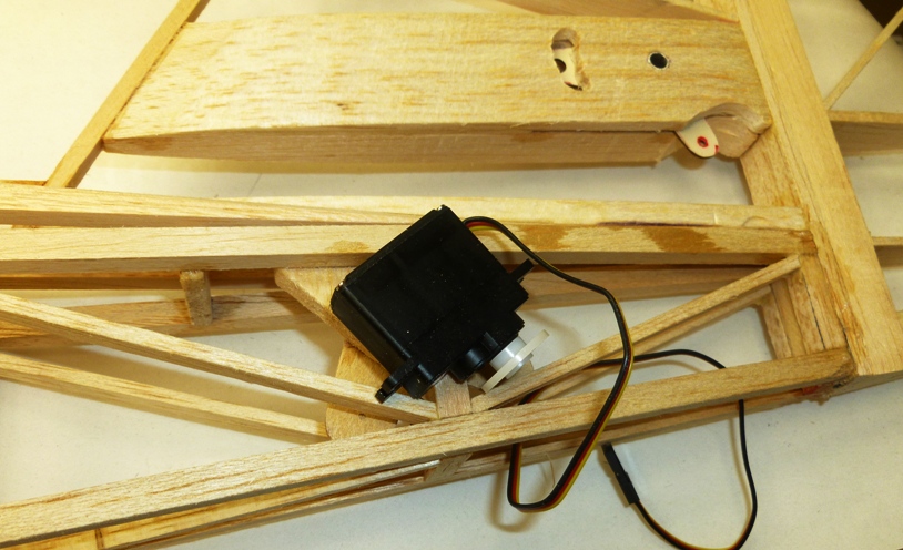
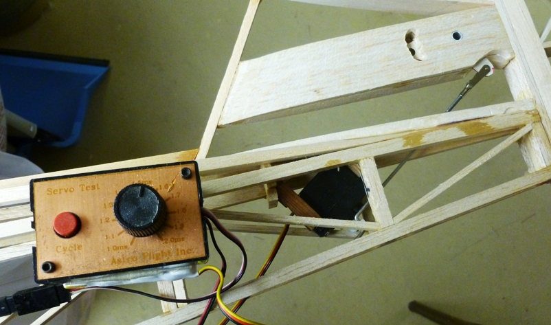
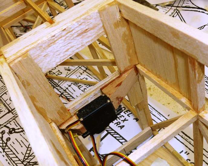
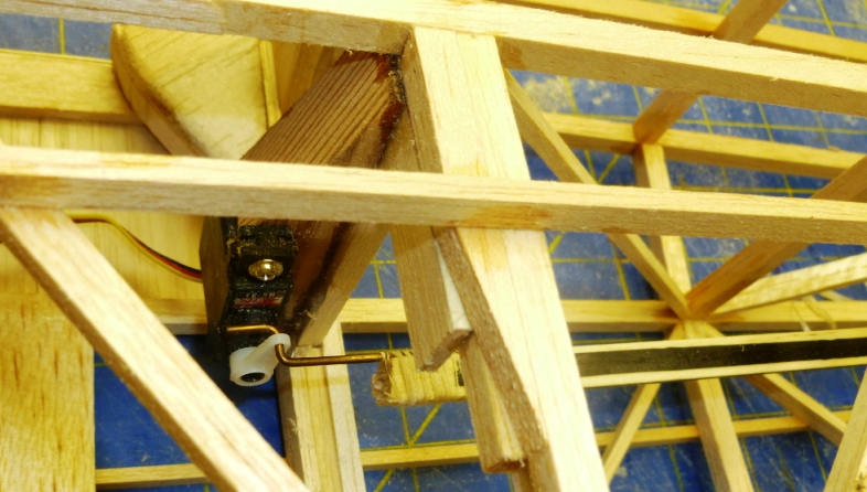
So I have decided to mount the servos aft and here is the elevator servo initial mounting with the pushrod wire sort of in place to show the routing and clearance. On my electric airplanes I usually glue the servo to a flat surface so the loads are taken in shear through the glue joint into the structure. But this airplane will have a vibration machine on the nose so I decided to use the manufacturer's screws and grommets. Here they mount into a pair of pine blocks which in turn are glued to the structure. I use an Astroflight servo tester to evaluate the servo and surface travel then set it to zero. Here the linkage is complete, installed and travel verified.
Well, changed my mind and have mounted the rudder servo forward. I will make a custom "magic" pushrod from light balsa and graphite!
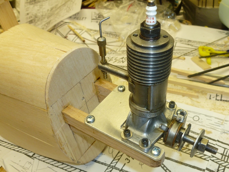
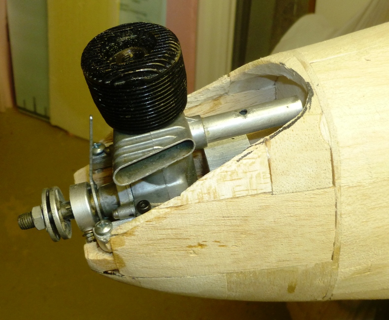
Next I went back to the engine mounting and fiddled around with both Brown and Ohlsson fitting. The Ohlsson thrust line is 3/8 inch below the mounting surface and the inside clearance about 1/8 inch more than the Brown. Also I found that having installed the bearers for 5 degrees downthrust I have the thrust line too low at the propeller location. So I decided to add some more bearer structure above the existing installation. I cut the new parts to sit on the existing bearers as parallel oak stock back to the firewall then taper off towards the back. After the glue set I then tapered the lower bearers at the forward end. This picture shows them before trimming and the subsequent engine shots after the trim.
I will mount the engines to aluminum plates which in turn mount to the bearers. i will standardize the plate attachment points to the bearers so I can make other engine installations interchangeable.
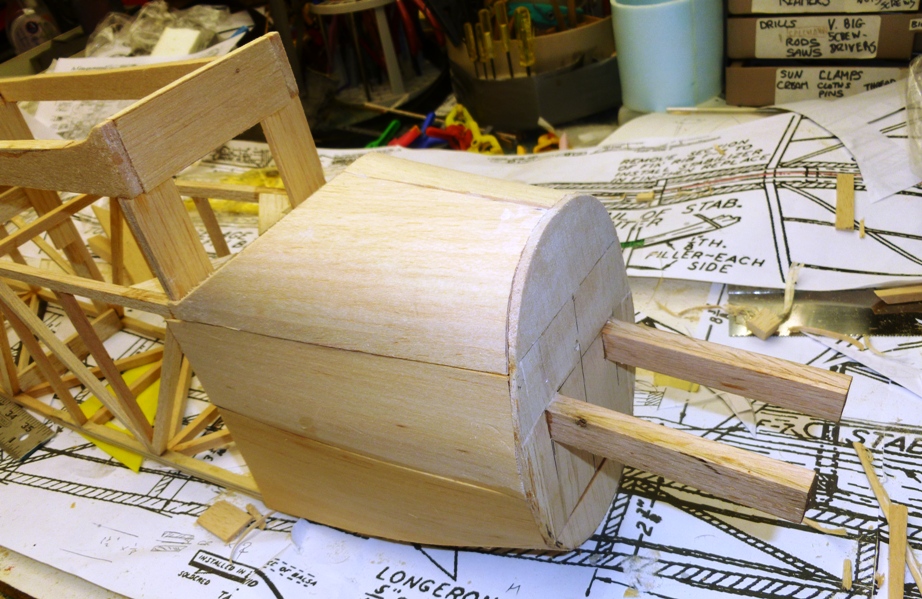
Now to attach and form the nose blocks.
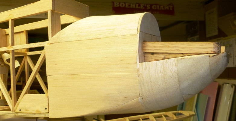
Now for the upper part or cheeks. Have to be careful to provide access and clearance for all the various functions etc. like the Ohlsson exhaust and timer arm. I will also carve out a sump and install a drain pipe, probably glue in a soda straw, although maybe I should wait till the finish is applied.
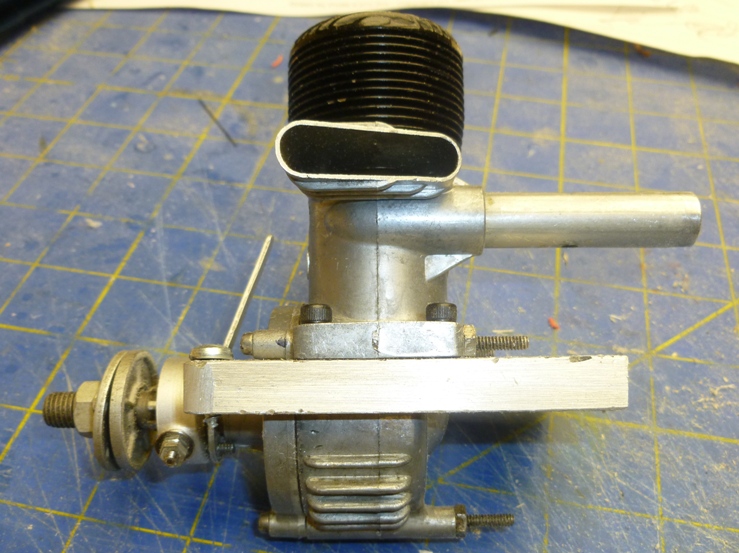
Here is the Ohlsson on its mounting plate. I have noticed that the bottom surface on the mounting lugs is not flat! It has the casting draw angles either side of the center molding / casting line. I will file them flat and true before the finall assembly. Makes you wonder how many people over the last seventy years have just screwed them down distorting the case and possibly the cylinder in the process.
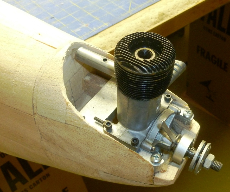
Her is the trial installation showing the multi piece upper cowl now carved back to clear the Ohlsson installation, which is more demanding of clearance than the Brown. This is still a crude fitting and maybe more balsa will be added and carved back for a better finish and structure. I will probably glass these parts for durability when done. It is going to be hard to choke this beast, maybe will need a special choking stick. Seems like I will have to make a special fuel tank to fit in this space.
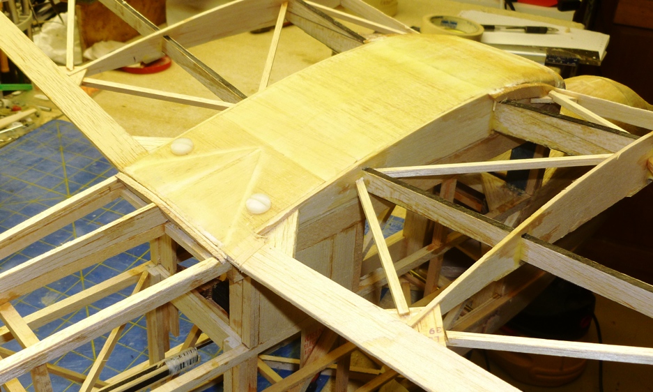
Meanwhile I have been thinking about the wing attachment. Originally I thought I would just use the usual rubber bands until I sorted the incidence etc. but I think I will instead make a LE dowel and TE nylon screw attachment. It is much cleaner and holds the wing alignment better. This will also allow me to make the original aft wing to fuselage upper fairing smooth all the way back. So I began to think about the mounting and all the necessary parts and strengthening necessary. Most of this will be in the center section of the wing and maybe the first outboard bays. So I began by measuring the wing assembly alignment. If some of you wonder if there is something wrong in this picture, it is probably because it was taken in my wife's fiber arts workshop!
I had found that the wing structure at this point was very soft in torsion. This is not surprising as the torsional stiffness results primarily from differential bending between the two spars, and at this point in the construction they are only connected by the 3/32 inch ribs. Eventually I will add the diagonal pieces between the ribs although the plan shows these to be 1/8 inch square members. These will do nothing for the torsional stiffness, so the element that will add the most will be the covering, and I just may use Fibafilm for this on the wing. The structure as it exists at this time, when all parts are connected, twists along its length, from tip to tip when loosely constrained at the center section. Twist the RH to wash-out and the LH tip twists to wash-in! This is because the two spars are very stiff. Lift the main spar on the LH side and it drops on the RH side. So the alignment very much depends on the seating or twisting of the center section when clamped to either a flat surface of the fuselage cabin crown. Once I make this part stiff and strong it will determine the incidence alignment of both wing halves, so I made some alignment measurements; eyeballs across carbon rods taped to inboard and outboard ribs. This suggests I need to shim one side of the center section a small amount, but I had better do it before proceeding with adding the rest of the wing structure.
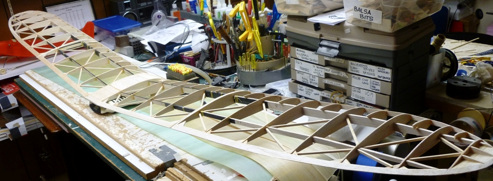
So here is the 95% finished wing structure with all the just less than final shaping of the LE and rib to LE and TE fit. Also added the diagonal pieces per plan, well almost. I also doubled up the interfacing ribs at the wing joints so as to make a clean joint and minimize the potential distortion from covering shrinking loads.
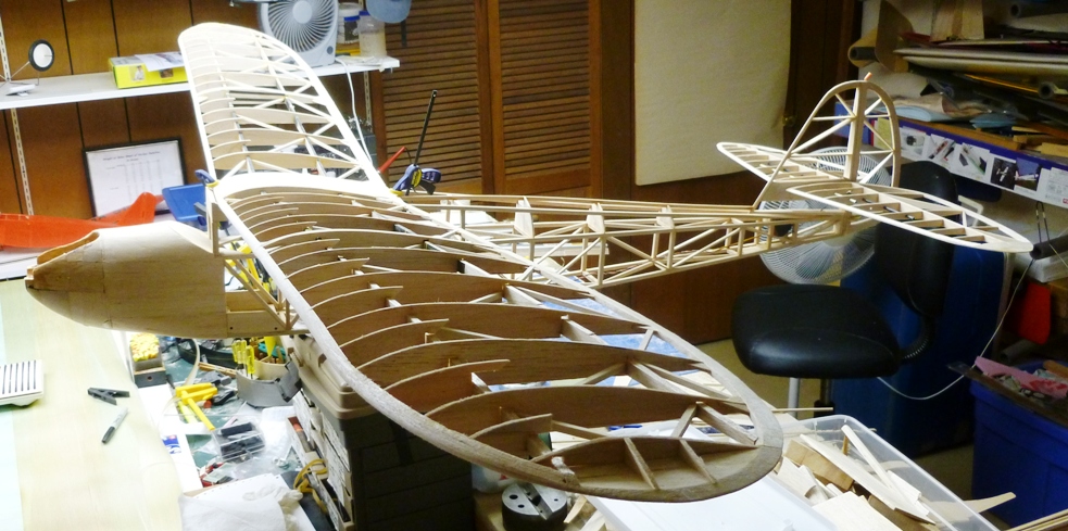
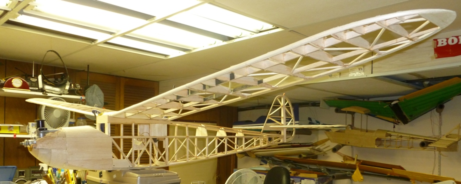
And here is how the 95% airframe looks with the wing sitting in place but not yet mounted structurally.
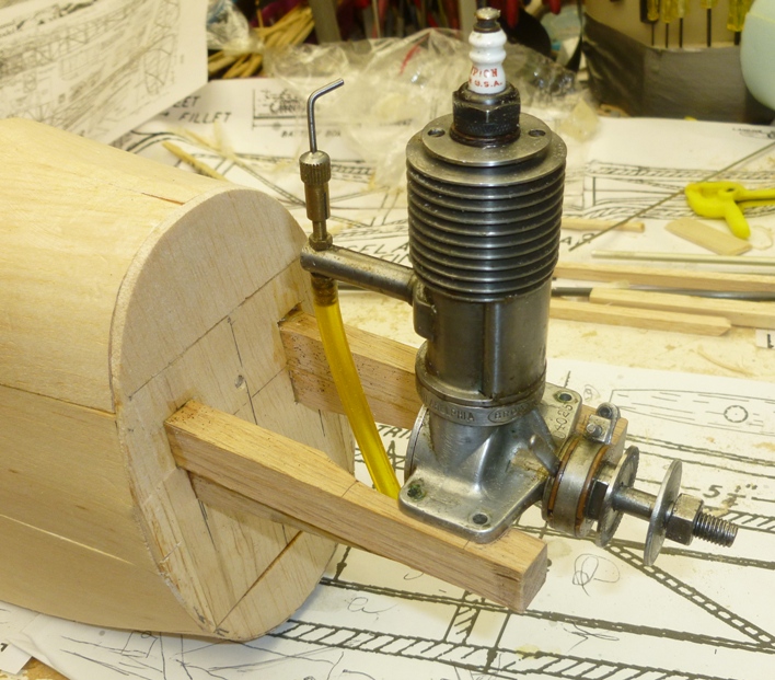
And with the Brown sitting in place so I can get a CG check. Too much trouble to find a clean background for these pictures tonight, but what the heck, it is a working shop!
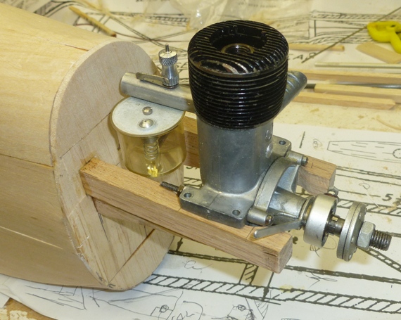
And with the Ohlsson for the CG check.
On the lines of the fuselage shaping stringers, the Gas Camera Model plan has the fuselage side below the cabin/wing as a flat surface with the shaping stringers aft and forward. I recently asked if anyone had an original plan for the Westerner and did it show the shaping stringers to be continuous. Eut Tileston said they were continuous so I will make them that way.
Did that and also fitted the rudder pushrod. I made a hi-tech one from a lightweight 3/8 inch square balsa stick stiffened with a strip of graphite on all four sides. This is the lightest way to make a pushrod of given stiffness. I attached a Z bend wire to the forward end and a conventional threaded rod and clevis to the aft end. Slipped a piece of plastic tube at the aft end to keep the friction down and make a more tidy penetration of the covering in that area.
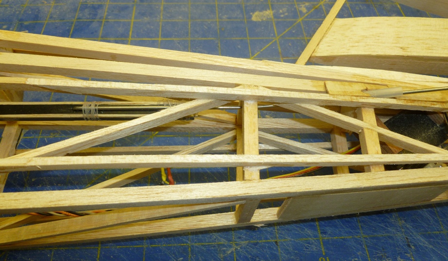
You can see a portion of the shaping stringers in this view.
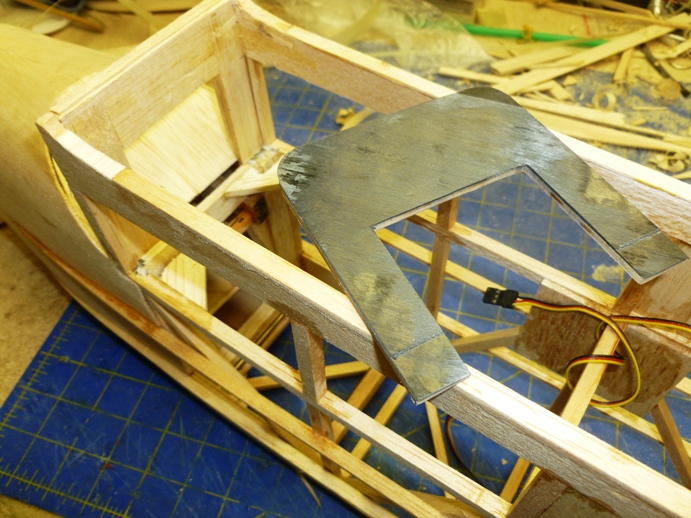
Next I will fit the wing to fuselage joint and associated structure. The mount will be with two dowels in the strengthened leading edge interfacing with a reinforced ply bulkhead at the front of the cabin. Two nylon screws will hold down the trailing edge. The reinforcement is in the form of two layer of +/_ 45 degree uni graphite to form a total of four layers. the orientation provides the best strength in all directions and in this application the wing lift loads flow through the dowels into this frame, then outboard to the existing former so it needs strength in several directions. I am using West 105/205 epoxy so as to get good strength and higher glass transition temperature. I have a bad habit of leaving my models in the van for days on end after a flying session. It sits out in the sun all day and internal temperatures have reached near 130 degrees. A while back I had some wing joiners creep out of shape under the weight of the wing while sitting in the van. In those I had used 30 minute epoxy and obviously the Tg was much too low. I know you can post-cure these parts as the glider guilder frequently do, but the West system is a better choice. The downside? Well it takes much longer to cure so I am now awaiting the heat lamp to speed things up so I can trim and mount the frame then drill the wing dowel holes.
Here is the frame and reinforcement.
And the trial installation.

The vertical over reach provides strength margin against dowel pullout and mounting for a forward upper fairing. this will fair the windshield and wing forward surface. But first to check the wing alignment before drilling the dowel and hold down screw holes.
Once I get the wing mount finished I can cover the wings. I will clean up the wing fairings before I can cover the fuselage. The empenage is ready for coveing too. Trouble is, now I have to decide on the covering and other finishing details. Oh, got to fuel proof the forward structure and any other place that migh be contaminated, like the inner ends of the horizontal tail halves and the fin structure that is exposed to exhaust where the horizontal tails attach. I have already fuel proofed the interior of the engine compartment with epoxy.
Finished the wing mount and fairings also applied water based PU sanding sealer and tissue to the sheet wood surfaces to help fuel proof and provide a better base for the iron on covering where that is applied. I will continue with the sanding sealer and tissue in the areas which will recieve just a paint finish.
Looks pretty clean and is certainly firm and strong. That just about does it for the airframe. Tomorrow I will begin the covering.
Since the wing structure is still fairly soft in torsion I think i will cover them with Fibafilm, a really stiff plastic covering with a distinct long strand fiber reinforcement. Trouble is, I don't think I have enough to cover the whole wing in one color and I want to fly it this weekend (it is now Wednesday 31st July and the SAM 12 meet is this Sunday). May have to make a two-tone wing!
The heck with that, it is now Friday so I covered it this morning with Doculam.
Now to build the landing gear, figure out a rattle can color scheme, install the receiver and battery and make a mount for the electric motor as it is too late in the day to get sorted for an ingnition flight on Sunday.
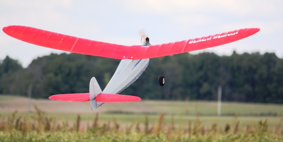
12 August, a week later, finally did some of that and even made the maiden flights. Flew pretty well after I got the subtrims set on the flying tail and bent the AXI outrunner motor mount to the right downthrust.
Now to paint the fuselage and order some graphics. Then run the sparkers and fly it with them.
Paint complete (except for fuel proofing the striping), balance and ballast set. Put it in the box this weekend for shipping to the Champs.
Oh, should order the graphics from Calie Hand.
Dec 2016
Thought I had better update this blog.
Had all kinds of interference into the elevator channel. Solved it by moving the elevator servo to the front of the fuselage and adding a pushrod for control. Problem solved and Brown Jr. behaving magnificently.
I have been flying the Westerner with the Brown Jr at the Champs and Eloy.
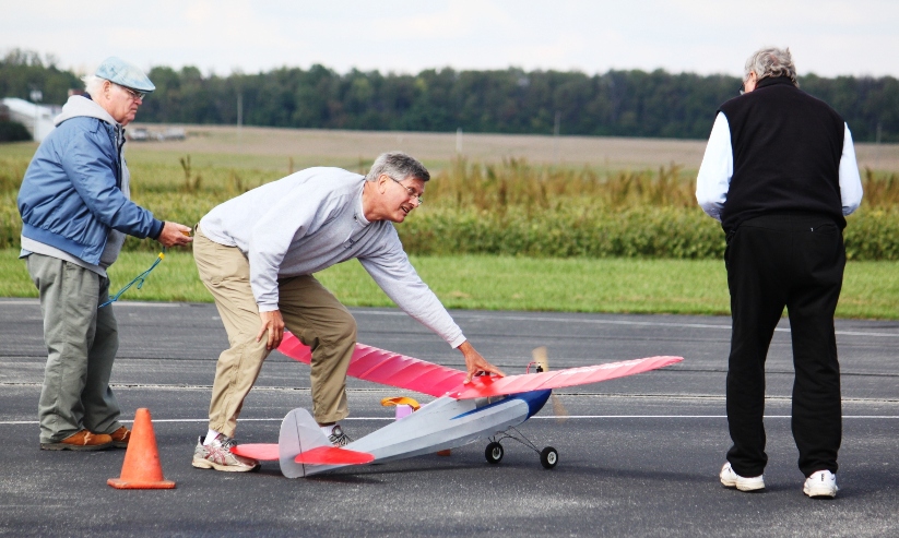
This year we flew at the 2016 Muncie Champs and had one magnificent 20 minute flight in Brown Jr. Texaco. Here we are for the flight;