
This is my attempt to document the progress of the Widener 2012/13 SAE Aero Design Competition Team activities from the late build stage through some flight testing and then on to the Competition. Here is the team;
The first parts of this blog are articles from the Propstopper's RC Club Newsletter, for which I am editor.
Dave Harding
Each year a team of senior engineering students at Widener University compete in the Society of Automotive Engineers Aero competition. This event requires them to design, analyze and fly a model airplane using an OS FX61 engine to carry the greatest payload and takeoff in 200 ft or less, landing in 400 ft or less. The students must also write a report describing their design and its rationale. It must also predict the expected performance and the score reflects not only the actual performance but also how accurately they predicted it An article on this event was included in a recent Model Aviation article which described the activity for the West Coast flyoff. This took place at the Sepulveda Basin's Apollo Field, one of the flying sites I visit on my SoCal stays. Dave Bevan has been supporting the Widener students for many years and I have for about the last four or five. Chuck Kime has joined us this year to help with the engine and prop testing shown here.

There are other rules, among them is the maximum dimension; span plus length plus height. This latter rule leads to some interesting configuration options.
| Specifications |
|---|
| Must be able to take off within three minutes |
| Take off within 200 feet |
| Once airborne, must complete one full circle of the field |
| Land within 400 feet |
| Combined dimensions (height, length, and width) < 225 inches |
| Fiber-Reinforced Plastic is prohibited on any part |
| Engine is an unmodified Mangum XLS .61A with an E-4010 Muffler |
| Procure payload (homogenous mass absent lead) |
| Aircraft (payload and fuel) ≤ 65 pounds |
The design logic starts with the available thrust both during the takeoff run and in flight. The in-flight thrust determines the maximum drag that can be overcome.
The next step is to define the lifting surfaces and their airfoils ~ this in turn defines the maximum lift. Since the span of the tail does not increase the dimension of the airplane in these rules, you can make it bigger than required for stability so it can carry a portion of the lift. Now because the tail is flying in the wake of the wing it does not lift as efficiently, in other words it produces more drag per increment of lift than does the wing. But since you need a tail for stability and the drag of that is included in the total it follows that some increment of lift is almost free and there is an optimum size.
Here is the result of their design process;

The Widener students making progress in constructing their entry in the SAE Aero competition. The model has a twelve foot wing with two foot chord and a large close coupled tail shown here. They had the ribs laser cut from CAD files they developed. The model will be expected to fly powered by an OS FX61 at about 55 pounds gross weight of which 40 pounds will be payload. They have managed to find some tungsten rods for the ballast making the payload box as small as possible. The rules forbid them from using lead, nor can they use fiber reinforced structures. Watch this space for updates as the model comes together and flight tests begin in the February time frame.

Widener University Students SAE Aero Team Make Progress


The Widener University team has made great progress this month, which is just as well because the competition is right around the corner. They will fly at the West Coast location in Los Angeles the weekend of the 12th of April. They finished construction a few weeks ago and began testing.
The initial test was for taxi stability and general shakedown with just the wing center section and fuselage components. The tests were conducted on the Widener hockey field, then the parking lot on a weekend. But the real progress was to obtain permission to fly from the old Bridgeport NJ airport site. Widener students and Dave Bevan used this site years ago but in recent times they and everyone else were chased off by the police. However, the site has been sold and one of the Widener students went over and asked permission to do their testing there. Better yet, the runway has been recently repaved, albeit a rather narrow strip. Nonetheless this is a priceless advantage as they can now fly at maximum weight and not worry about tracking in a soft grass strip.


The site and weather were perfect and so was the takeoff.


Unfortunately the handling qualities were not and Boeing engineer test pilot, Pete Noel, a veteran of twenty years Widener first flights, had a really hard time controlling the model in the roll axis.
This model has a very aggressive airfoil, designed to make at least 50% more lift that a conventional cambered section. The ailerons were set to about 20 degrees up and 10 degrees down in an attempt to provide complementary yaw with roll i.e. given a roll control input the model would also yaw slightly in the direction of the turn. However, in the event the roll control was highly nonlinear, indeed it might have caused a reverse upset as the attitude and control input increased. In the following sequence from the movie you can see the ailerons hard over to pull out of the right roll but the turn remained tight, and may have even tightened up.

There were periods of flight that appeared stable, but the model remained uncontrollable and eventually cart wheeled into the soft mud off the strip. Both removable tips were destroyed and the wing center section damaged.
However the eager crew quickly built new wing tips and repaired the center section.
The repaired model design was revised to incorporate parallel chord tips for easy of construction and incorporated full tip-span ailerons which were mechanized to only move in the up direction. The team believed perhaps the outside of turn aileron downwards deflection was causing tip stall with the aggressive airfoil. So to turn left the left aileron moved up while the right aileron stayed in line with the airfoil. More dihedral was also incorporated in a further attempt to improve roll stability and enhance the capability to use rudder in turns.
A second test flight was then made at Bridgeport, also in good weather conditions.

Unfortunately the second flight also exhibited extreme roll uncontrollability and also resulted in a cart wheel arrival. This time the damage was even less than the first, being mostly concentrated to the right hand tip section and fuselage nose, which has a breakaway set of nylon bolts connecting it to the center section wing spar.

For this flight they had an airborne key chain camera mounted above the wing on the tail boom looking aft. They had expected to witness the activities of the elevator and model pitch upsets, but didn't get the aim right. Nonetheless when viewed as side by side videos ground and airborne they were able to get a much better view of the model's behavior. The next flight will aim this camera towards the wing tips and ailerons. The surfaces will also be tufted like the big boys do when trying to understand airflows.


Repairs are at hand and further forensics in work, mostly associated with the effectiveness of the ailerons.
March 31st.
The Widener students have continued the development of their SAE Aero Competition entry with a great deal of frustrating results. The fundamental problem is one of roll and directional control. Basically the airplane falls off to either side and does not respond to aileron correction inputs, as you see in these photos from the flight movie.

The development of the aileron control started with tapered wing tips with fairly small ailerons mechanized to give twice the up travel than down (see last month's newsletter. You do save them don't you?). This was done for the usual reason; i.e. to minimize or eliminate adverse yaw.
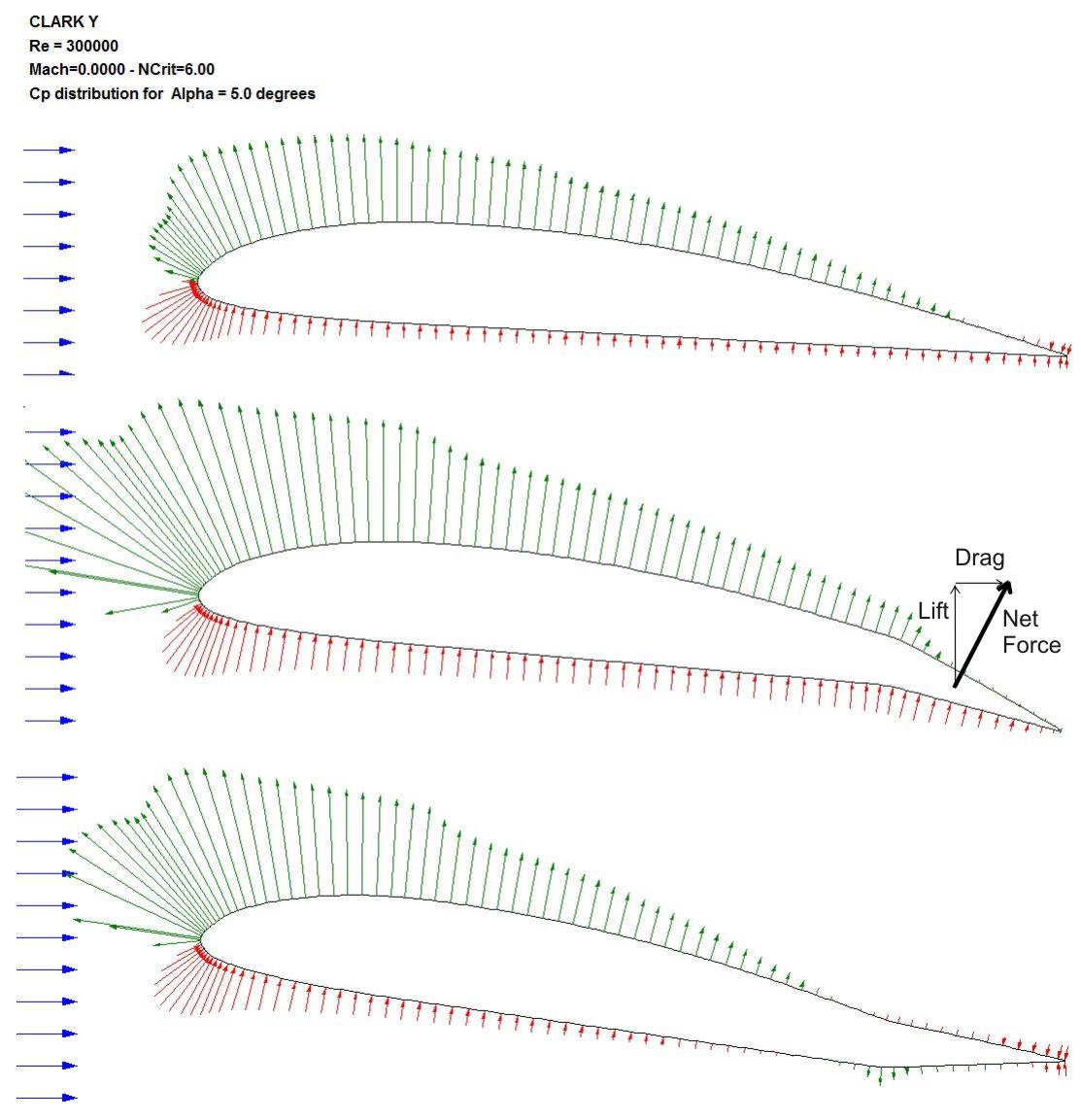
If you are flying an aerobat you want ailerons to provide roll control with no change in any other axis. Unfortunately in steady forward flight an aileron that moves down generates more drag than one that moves up the same amount. This causes the airplane that is rolling to the left, to yaw to the right, and if there is any dihedral in the wing, or dihedral effect due to the wing placement on the fuselage, this effect causes the airplane to experience a right roll moment. The two effects can cancel each other out resulting in the airplane flying straight but with a roll and yaw attitude; Not desirable! Here are the pressure distributions around a conventional Clark Y airfoil with a +/- 10 degree aileron deflection. The pressure is positive with the red arrows and negative (suction) with the blue and the length of the arrow is the magnitude of the pressure at that point.
Note there is very little pressure on either surface on an aligned and up deflected aileron and as a consequence, little or no drag increase. The down deflected aileron shows a marked positive pressure below the aileron surface and indeed the whole airfoil lower surface this pressure integrates over the tilted surface into a lift force (intended) and a drag force; unintended or undesirable.
So the usual fix is the aforementioned practice to have the ailerons with greater motion up than down, thereby either cancelling the adverse yaw or even enhancing the turn with proverse yaw (opposite of adverse, commonly used in this context, but not in the dictionary!). And this the Widener team did on the first configuration; but it didn't work and control was essentially inoperable; the model crashed.
The model was rebuilt with new tip sections, this time with a parallel chord for ease of construction and full length ailerons. Dihedral was increased to 8 degrees on the outer panels with the expectation of some turn control via the effective rudders. The aileron motion was changed so they only moved up. The thinking being that perhaps the wing was stalling with down aileron motion with this highly cambered airfoil. Warps were noted in the original configuration and these were removed. This is the model configuration shown in the photos above. It still had essentially little or no roll/directional control although two flights were made in still air with successful landings.
The next flight was made with an on-board aileron camera with flow tufts to explore the flow patterns around the ailerons. The CG was moved slightly forward to enhance pitch stability which was a bit twitchy on the earlier flights. The flight was made in fairly high winds and a slightly higher weight. It ended after the first turn downwind after takeoff when performance and loss of altitude in the turn brought the model to treetop level. An avoidance maneuver caused the model to once again spiral in. But we had some aileron flow data to examine.


The flows were nicely attached and aligned in yaw and with the departing flows. So it seemed that the ailerons were working properly, but still they didn't have control. But on comparison with the calculated pressure field the flows seemed a confirmation. So how do we get the combination of roll and yaw that is desired? Here is the team after the 4th flight.

The next configuration tried in flight was based on the observation that the tailplane is huge; six feet span actually. With large elevators it looked like an ideal opportunity to try operating the elevators as elevons, so they were split in two and an additional servo added to provide the necessary control configuration. It was decided to leave the ailerons in the closed position but provide a roll trim capability via the transmitter knob. The plan was for your editor to "man the knob" while Hot Hands Pete, the Boeing engineer pilot was on the sticks.
Unfortunately this was a complete failure as the control was nonexistent and cranking the knob did no better than the original mechanization of the ailerons through the sticks. The model quickly crashed into the trees giving the team another major rebuild. Here is a summary of the flights todate;

So back to studying how the ailerons might be made effective. We examined the pressure distributions on the Epler airfoil with ailerons and discovered that the drag actually decreases with an up turned aileron compared to the neutral condition so the proverse yaw case applied even when we restricted the ailerons to only move upl

The clue was provided by watching some of the YouTube videos of other competitive planes flying in the competitions. We looked at those with similar highly cambered airfoils and found one that was controlled with spoilers on the upper outer surface, like today's jet airliners.
First we discovered a 1934 NACA paper on tests with the Clark Y airfoil equipped with various ailerons, split flaps and spoilers. The conclusion was the most effective location for a spoiler is at 30% chord but that would mean a change from the design specified in the team's design report; a loss of points event. But one of the team suggested we make split ailerons as they would probably act as adequate spoilers and had two other advantages, first they could be retrofitted to the existing model and second, probably didn't constitute a change from the reported design; They didn't specify what kind of ailerons, only their position and size!
So the change was first examined analytically. Computing the pressure distribution similar to those above using Profili Pro proved too hard to conquer, but one of the Widener guys used Martin Heperle's javafoil to produce these pressure distributions. The stagnation (high) pressure behind the split aileron is clearly apparent so it was expected the desired proverse yaw and favorable roll would be achieved with this approach. All that was necessary was to make the repairs to the model from the last arrival and incorporate the split ailerons.


In the photos below from the test flight on 23rd March you can see the split aileron behaved just as the analysis predicted. In the picture below you can see the tufts on the upper aft end of the aileron have been sucked back under the aileron into the cavity below; just like the analysis sugested. And better yet, the model was controllable although the flight was rather like Mr Rabbit's Wild Ride at Disneyland. But the model survived and a continuing series of flight tests are planned as they build a second and third model to be shipped to California for the competition

Four subsequent flights were performed on the 4th of April. These tests were aimed at selecting the best propeller by making heavy flights with full acceleration, just like the competition flights, and takeoff distance was measured. The flights were made with 30 lb of payload so the gross weight was in the order of 46 lb. In the picture below Chuck Kime is standing at the 175 ft mark.


The results of these tests are;
| Prop, APC |
Takeoff distance ~ ft. | rpm | Video |
| 12x8 | 220 | 10,500 | No |
| 14x4W | 195 | 9,800 | Yes |
| 14x7 | 195 | 9,500 | Yes |
| 13x7 | 200 | 10,500 | No |
Following these tests the prototype was dissassembled and the essential parts readied for shipment.